


After Dartmouth College installed solar panels at a remote campus site built for research and instruction, its administrators grew tired of relying heavily on its noisy generator in the evening, particularly during the coldest winter months. On cloudy days, when less solar power was generated and when research extended into the evening when solar power was no longer available, faculty and students had to continually revert to using their generator. They longed for a silent, maintenance-free, long-lasting backup power source to withstand their cold New Hampshire winter temperatures, which regularly reached 20 degrees below freezing.
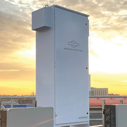
Dartmouth College turned to John Hassell of Be Green Solar to find the optimal solution. Having installed SimpliPhi Power (acquired by Briggs & Stratton in 2021), energy storage solutions for many years all over the East Coast, John highly recommended SimpliPHI-branded batteries.
“SimpliPHI batteries was the best choice for the area,” shared John. “PHI batteries offer superior performance, especially when evaluated against other technologies. Looking at the comparison chart, the lithium advantage is apparent. The PHI lithium ferrous phosphate (LFP) battery gives the user and installer advantages over other battery chemistries. The name ‘SimpliPHIi’ is not just a brand name; it represents a philosophy: using a SimpliPHI-branded energy storage solution makes the system simpler to install and maintain.”
PHI batteries can also operate and charge in an extremely wide temperature range; they can even charge at 32° F without issue, unlike most other lithium batteries. However, to enable the PHI batteries to function optimally at well below freezing temperatures and thereby protect the battery’s 10,000-cycle, 10-year warranty, John implemented a simple battery heating system, described below:

The battery box is constructed using a 0.75-inch medium-density fiberboard (MDF). The top and front of the box are removable to facilitate battery installation and maintenance. The top is secured with 10 thumb screws. All sides of the box, as well as the top and bottom, are insulated with 0.5-inch solid foam panels.
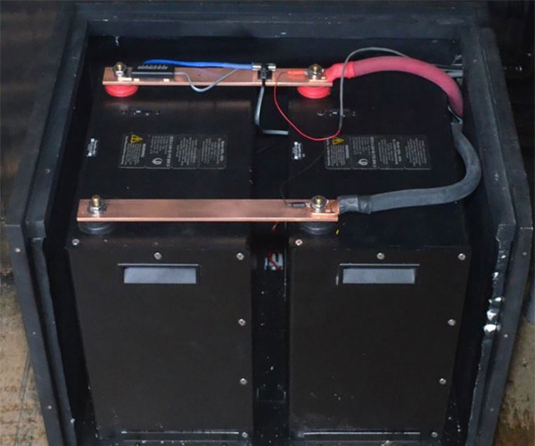
Heat is supplied by two 24V, 25-watt heating elements connected in parallel to provide 50 watts of heat. The batteries sit on a 3.0 mm aluminum panel, and the heating elements are attached to the underside of the aluminum plate, as shown below.


The heating pads are held in place by two aluminum plates. A thermal compound was used between the elements and the aluminum base to improve heat distribution. A 3-terminal barrier strip is used to connect the heating elements to the 24VDC power source and allow the elements to be connected in series (48V) or parallel (24V). While in operation, the elements heat the aluminum base plate, which heats the batteries. Power to the heating elements is controlled by the data acquisition system (DAQ).
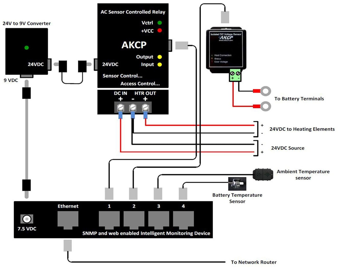
The DAQ, seen below, was installed to monitor the battery and ambient temperatures and control the box heating elements.
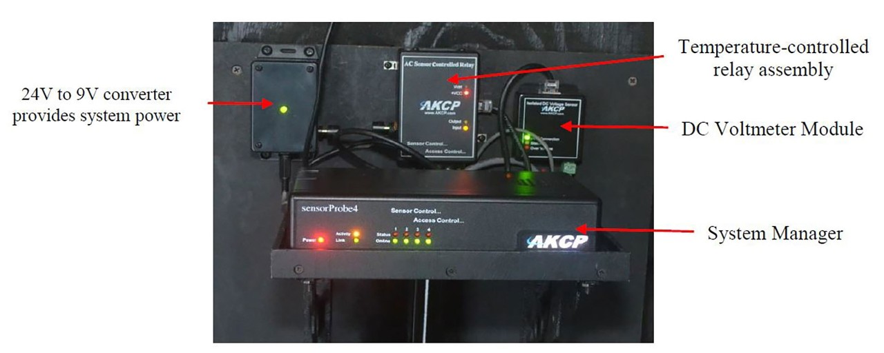
The 24V to 9V converter, pictured on the left in the above image, converts the 24VDC battery voltage to 9VDC to operate the System Manager. The system manager powers all peripheral elements. A 2 Amp fuse is mounted on the circuit board inside the box.
The temperature-controlled relay assembly, pictured in the upper middle of the above image, contains a 15-amp relay programmed to respond to the battery temperature sensor. When the battery temperature sensor drops below 38ºF, the relay energizes and supplies 24VDC to the heating elements in the box. The elements remain on until the temperature rises to 40-41ºF.
The DC Voltmeter Module, pictured in the upper right of the above image, monitors the batteries' voltage. The system is programmed to send an email alert if the battery voltage drops below 23.6 VDC.
The System Manager, pictured at the bottom of the above image, receives data from the temperature sensors and controls the heating elements. It also sends email alerts for virtually any programmable condition and connects to the local router via an Ethernet port.
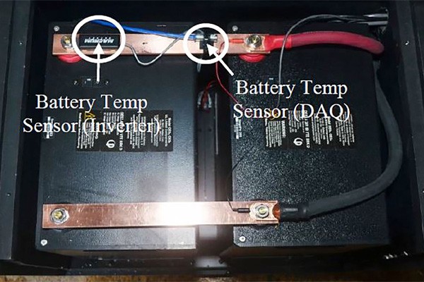
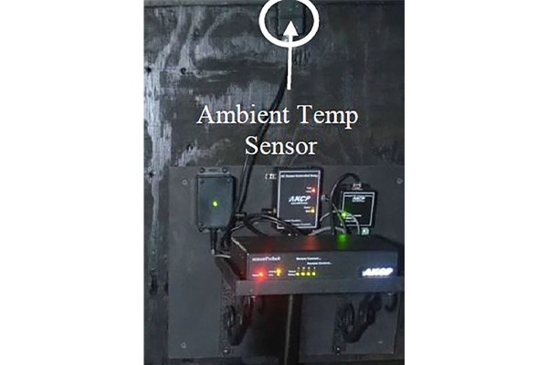
There are two sensors monitored by the System Manager; one monitors the ambient temperature of the room, and the other monitors the temperature of the batteries. There is a third temperature sensor that connects to the Magnum inverter, but it is not monitored by the DAQ. The Magnum sensor reports to the Magnum MagWeb website but cannot show temperatures lower than 32ºF. The temperature sensors can be seen in the images below.
The wiring diagram below provides details on DAQ wiring. The System Manager connects to a Cisco Wireless Ethernet Bridge, which transmits to the site router in the main building.
Programming this heating system involves setting the heater's on and off temperatures and thresholds for various email messages.
As for the temperature sensor thresholds, the ambient temperature sensor simply shows the room temperature. It is not programmed to send any email alerts. However, the battery temperature sensor is programmed to turn the heating elements on and off via the Relay Module. The associated alert thresholds are described below.
| High-temperature warning | 88ºF | Alert email sent |
|---|---|---|
| High-temperature critical | 90ºF | Alert email sent |
| Low-temperature warning | 39ºF | Alert email sent |
| Low-temperature critical | 38ºF | Alert email sent. Heating elements are turned on. The temperature differential is set to 2ºF. When the battery temperature reaches 40ºF, the heating elements are turned off. |
When it comes to battery voltage thresholds and associated DAQ alerts, the power system at the site is programmed to start the backup generator when the battery voltage reaches 23.8V. If the voltage drops below this value, it indicates that the generator has not started. The DAQ is programmed to send alerts under the following conditions:
| Low battery warning | 23.8V | Alert email sent |
|---|---|---|
| Low battery critical | 90ºF | Alert email sent |
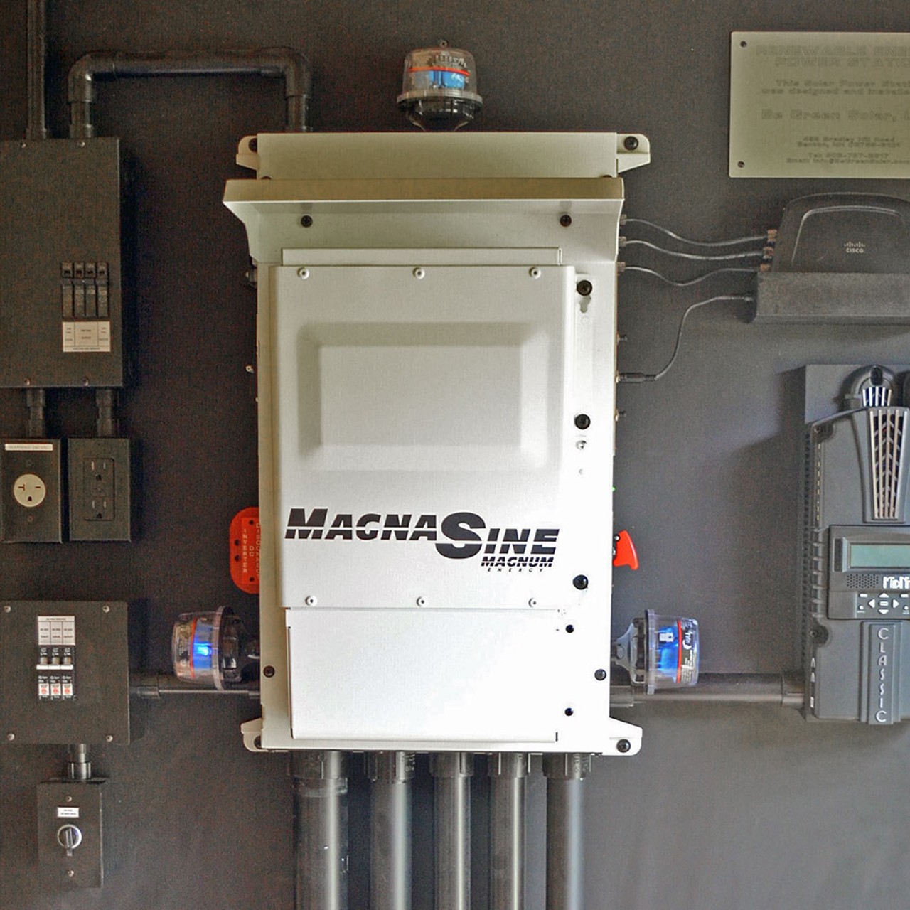
This solar+storage installation consists of two PHI 3.4 24V batteries providing 6.8 kWh of energy storage, a 1.8kW solar array, a 4 kW Magnum MS404PAE 120/240VAC inverter, and a MidNite Solar Classic 150 charge controller. It powers lights, ceiling fans, all faculty and student laptop computers, a refrigerator, outlets, as well as network and WiFi hardware.
Request a Commercial Consultation
Talk with a Briggs & Stratton energy expert by clicking the button below and provide basic information about your upoming project!