
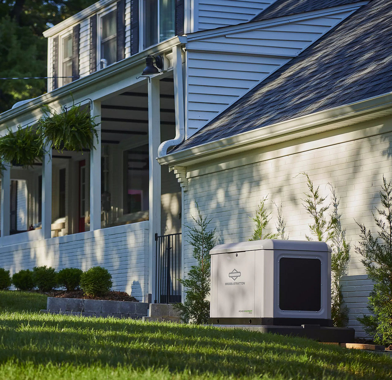

Standby Generators
NOTICE: THE ITEMS IN THIS SECTION ARE TO ONLY BE USED BY QUALIFIED SERVICE PERSONNEL.
Use the information below to help troubleshoot issues with a Briggs & Stratton air-cooled standby generator. This page provides common troubleshooting steps. Use of information provided here is not a substitute for reviewing the manuals and other relevant documents for the product you are servicing. The documents contain safety information to make you aware of hazards and risks associated with the product and how to avoid them. It is important that you read and understand the documents and instructions thoroughly. If you are uncomfortable working with electricity or fuel, please contact a qualified service technician.
Service scenarios may present themselves, including basic symptoms, potential causes, and ‘alarms’ on the GC-1030 Series Controller.
Choose from the following Quick Navigation Buttons to navigate to a specific service scenario:
Generator Does Not Start Generator Starts then Shuts Down Generator Runs Rough Generator Does Not Produce Voltage Generator Starts and Runs For No Reason GC-1030 Series Controller Alarms & Event Log
Briggs & Stratton Energy Solutions offers technical resources and guidance for other types of installation & maintenance scenarios.
For more in-depth electrical troubleshooting instructions, including important safety and warning information, navigate to the Technical Support Resources section and consult the Electrical Troubleshooting and Repair Manual (Air-Cooled Standby Generator with GC-1030 Series Controller) document.
Choose from the following Quick Navigation Buttons to navigate to these helpful resources:
Installation & Start-up Support Service Call & Maintenance Best Practices Technical Support Resources
If the engine in a standby generator will not crank, the issue is likely with the start circuit, such as a dead battery, or a faulty starter motor.
NOTICE - Whenever "Test again" appears, install the 15 amp fuse (see your generator's installation and operator's manual for the fuse location), if removed. From MANUAL mode (Engine Off-Ready), press START/SELECT on the controller to check if the engine cranks. If the test fails, remove the 15 amp fuse and proceed to the next step.
If a test passes, follow the linear steps to the appropriate section. If the engine begins to Crank, but does not Start, advance to Symptom: Engine Does Not Start.
Potential Cause: Weak/ Failed battery, battery charger, and/or battery connections issue
ALARM(S): Battery Under Voltage, Battery Over Voltage
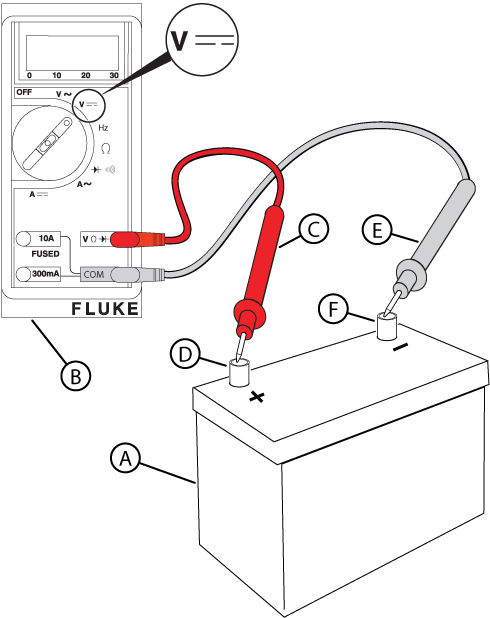
Figure 11
NOTICE - If you do not have an approved battery load tester, refer to the Battery Load Test section in the engine's repair manual (Part No. 80114787) for instructions on performing a battery load test without the battery load test tool.
NOTICE - Meter reading in steps 9 and 10 verify that utility voltage is present.
WARNING - Even if the terminals of Pin 1 (-) and Pin 2 (+) are back-probed as instructed, avoid touching both terminals simultaneously. Do not remove socket terminals and probe the pins directly, because touching both pins with the same probe will result in arcing between terminals. Any arcing can damage controller components and wires, and cause eye injuries if safety glasses are not worn.
WARNING - Fuel and fuel vapors can be ignited, causing explosion, which could result in death or serious injury.
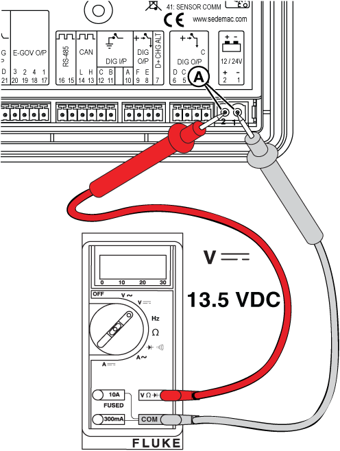
Figure 12
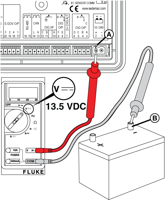
Figure 13
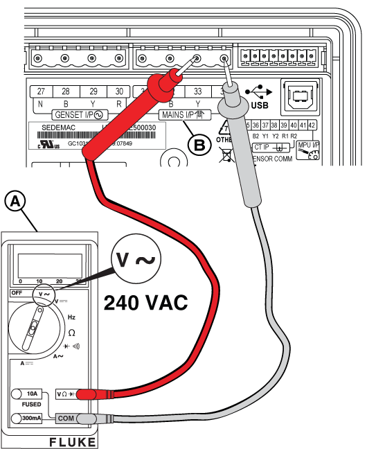
Figure 14
Figure 15
NOTICE - Before replacing the fuses, turn off utility power and remove the fuses from the fuse holder and verify that no continuity to ground is present. If continuity to ground is present, check for wire shorts or a failed battery charger, warmer, or controller.
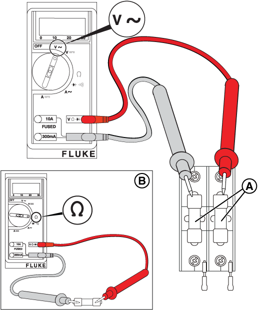
Figure 16
NOTICE - If a new battery is installed during a utility outage, the charging circuit must be tested after restoration of utility power.
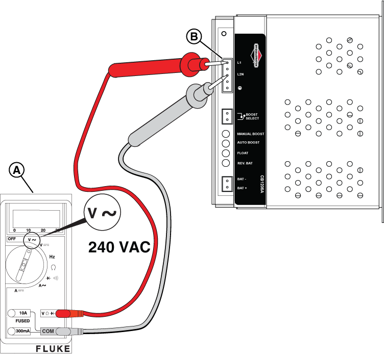
Figure 17
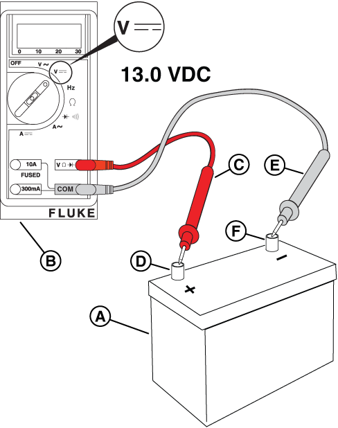
Figure 18
NOTICE - The relay board on 13 kW units does not have the 3-pin connector shown in the following images.
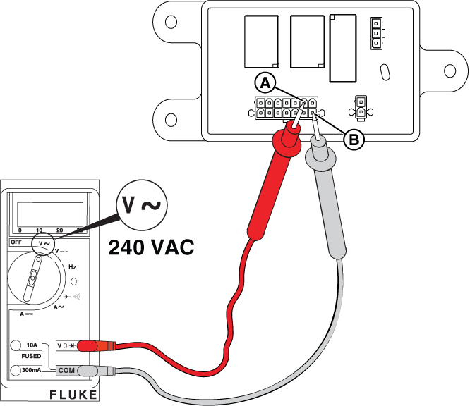
Figure 19
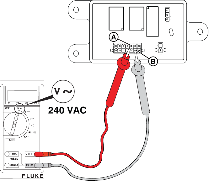
Figure 20
Potential Cause: Starter Relay/ Starter Solenoid component or wiring issue
ALARM(S): Fail to Start
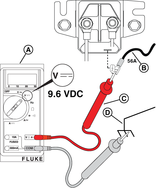
Figure 21
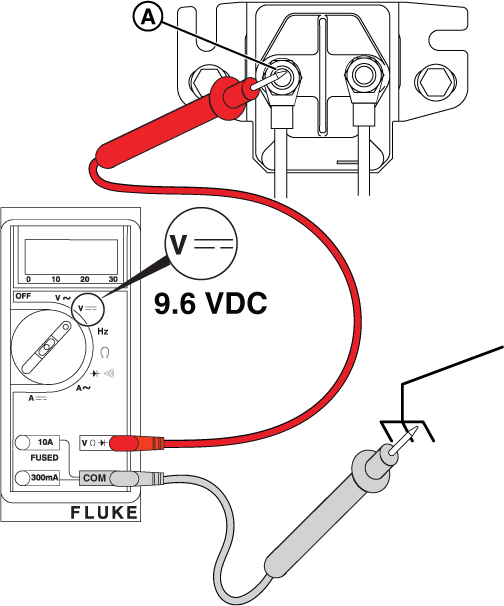
Figure 22
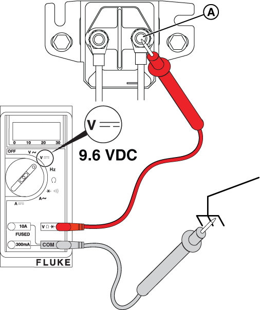
Figure 23
Figure 24
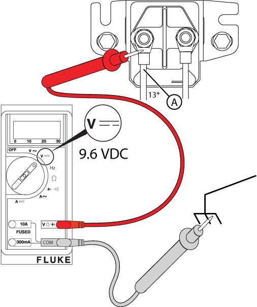
Figure 25
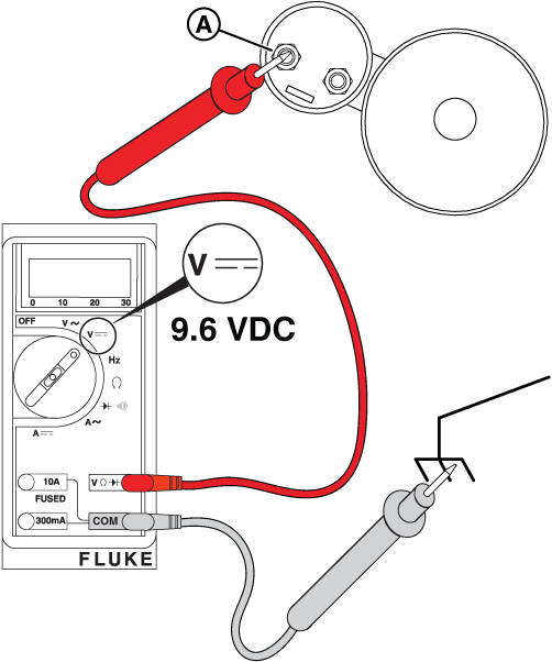
Figure 26
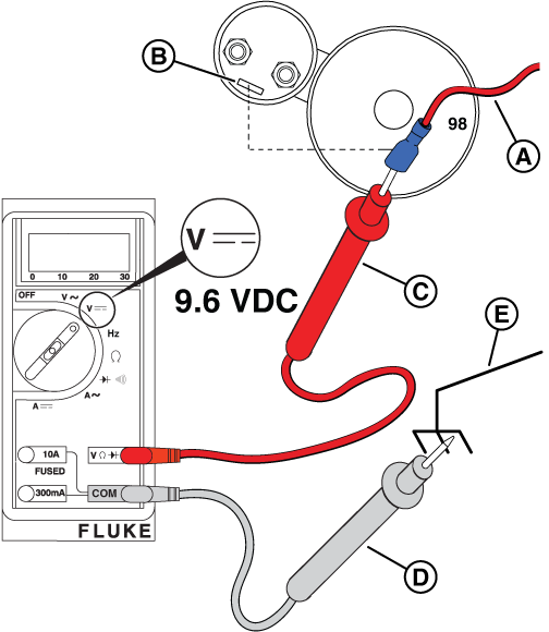
Figure 28
Potential Cause: Generator Controller or Relay Board does not output ≥9.6 VDC
ALARM(S): Fail to Start
At the Controller
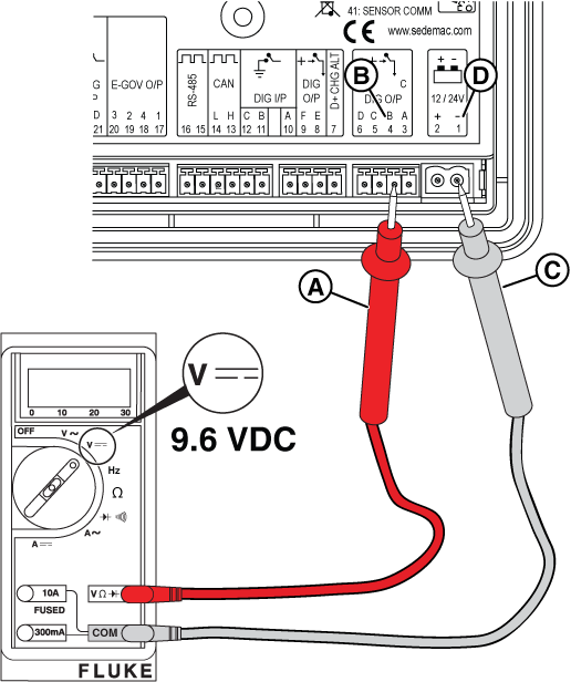
Figure 29
At the Relay Board
NOTICE - The relay board on 13 kW units does not have the 3-pin connector shown in the following images.
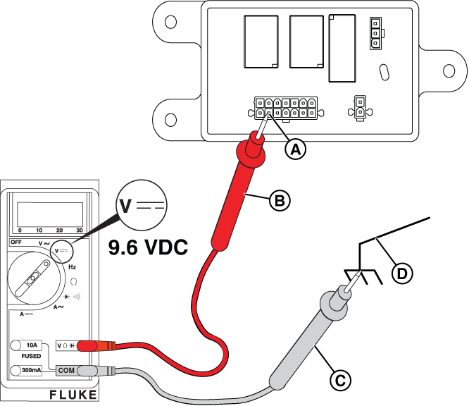
Figure 30
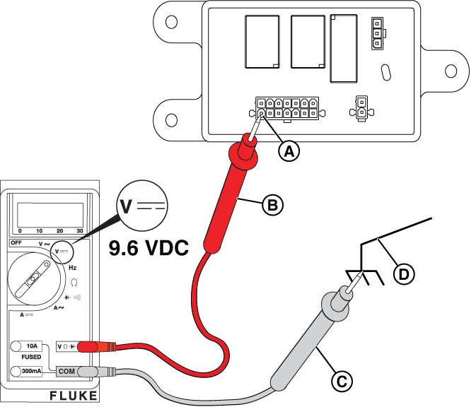
Figure 31
Potential Cause: Emergency Stop button pressed, and/or wiring connection issue
ALARM(S): Emergency Stop
Potential Cause: Generator Controller in MANUAL/ Engine Off mode
ALARM(S): N/A
NOTICE - If a fault is present on the controller, go to GC-1030 Series Controller Alarms & Event Log and review the corresponding fault displayed on the controller.
An engine in a standby generator that does not start can be caused by a variety of issues, with fuel problems, electrical problems, and mechanical issues being the most common. Troubleshooting typically involves checking oil and fuel levels, the battery, spark plugs, air filter, and the choke.
Potential Cause: Engine Oil Level is Incorrect/ Insufficient (Low or No Oil)
ALARM(S): N/A
NOTICE - The most accurate oil level readings are obtained when the engine is cold.
NOTICE - Check the oil level on both sides of the dipstick.
NOTICE - Dispose of used oil and the oil filter at a proper waste disposal or recycling center.
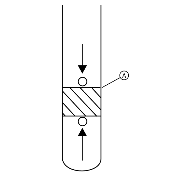
Figure 83
Potential Cause: Fuel Pressure is Incorrect/ Insufficient (Low or No Fuel)
ALARM(S): Fail to Start
NOTICE - Fuel is only present on units with a liquid propane (LP) supply tank.
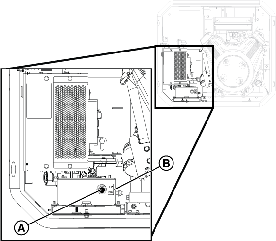
Figure 3
| 12-13kW NG and LP Configurations | |||||
|---|---|---|---|---|---|
| Model | Engine | Frequency | Fuel Type | Main Jet Turns | Idle Jet Turns |
| 12kW | BSPP 38 v/s | 60 Hz | NG | 1/2 | 2-1/2 |
| LP | 0 | 1/4 | |||
| 13kW | BSPP 38 v/s | 60 Hz | NG | 1-3/8 | 3/8 |
| LP | 1/8 | 3/4 | |||
Figure 4
NOTICE - If you are changing the setup in the generator's controller from the factory setting of NG fuel to LP fuel you will need to enter the configuration menu by using the Dealer Password, which is available on the Power Portal.
NOTICE - Selecting a profile that is not intended for the generator can cause the generator to run erratically and can result in damage.
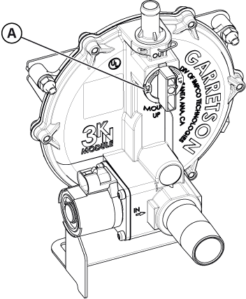
Figure 5
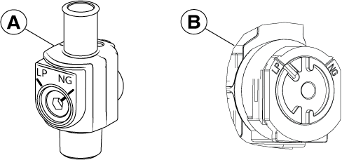
Figure 7
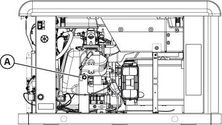
Figure 8
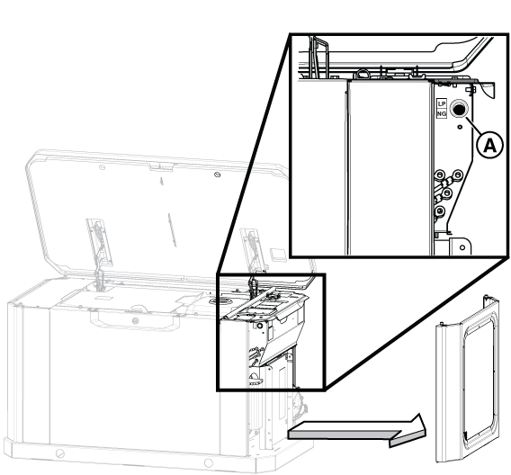
Figure 9
NOTICE - If you are changing the setup in the generator's controller from the factory setting of NG fuel to LP fuel you will need to enter the configuration menu by using the Dealer Password, which is available on the Power Portal.
NOTICE - Selecting a profile that is not intended for the generator can cause the generator to run erratically and could result in damage.
NOTICE - The generator inlet fuel pressure should be 11-14 inches WC (LP) or 3.5-7 inches WC (NG).
NOTICE - If a test port does not exist, see the appropriate installation manual for instructions on installing it. To proceed with troubleshooting in the absence of a test port, go to step 4 of Check Fuel Solenoid and Thermal Fuses to use the test port in the fuel pressure regulator (B, Figure 32). Although use of this port will indicate whether fuel is present, it will not indicate whether the incoming fuel has dropped in pressure.
NOTICE - No more than 0.5 inches WC drop should be seen between static and dynamic fuel pressure and the fuel reading should be stable.
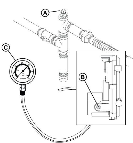
Figure 32
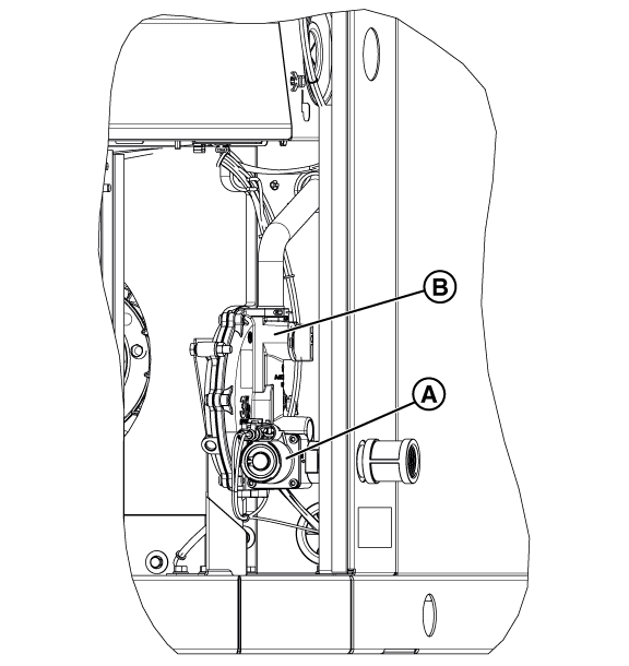
Figure 33
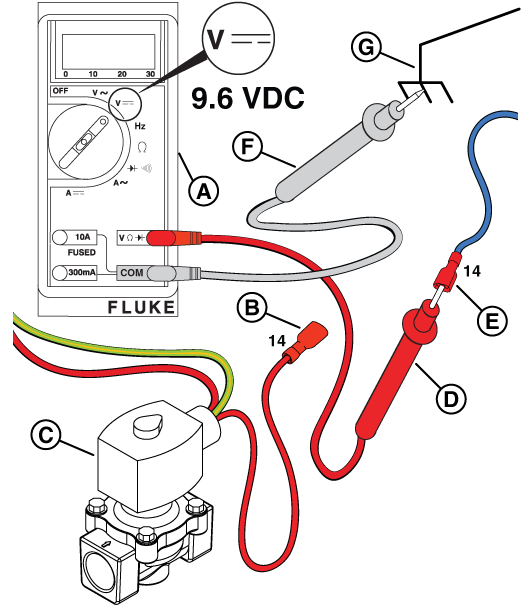
Figure 34
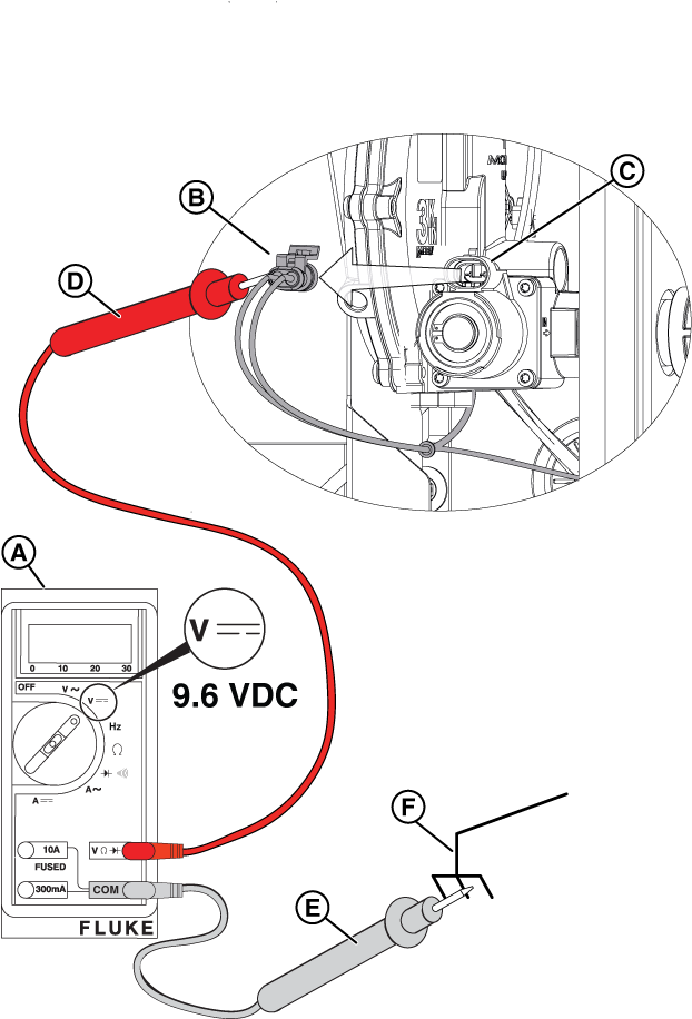
Figure 35
NOTICE - There will not be voltage at the pauses between cranks. When activated, a "click" is heard at the fuel solenoid and that indicates that it opened correctly.
NOTICE - Step 8 applies only to Fortress II generator units. If you do not have a Fortress II unit, skip to step 10.
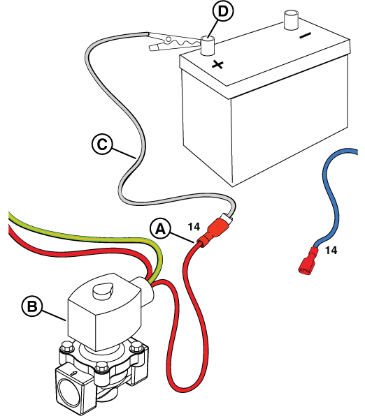
Figure 36
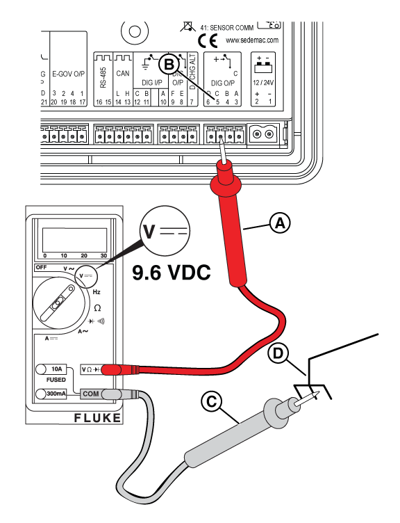
Figure 37
NOTICE - The relay board on 13 kW units does not have the 3-pin connector shown in the following images.
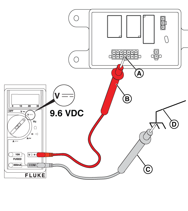
Figure 38
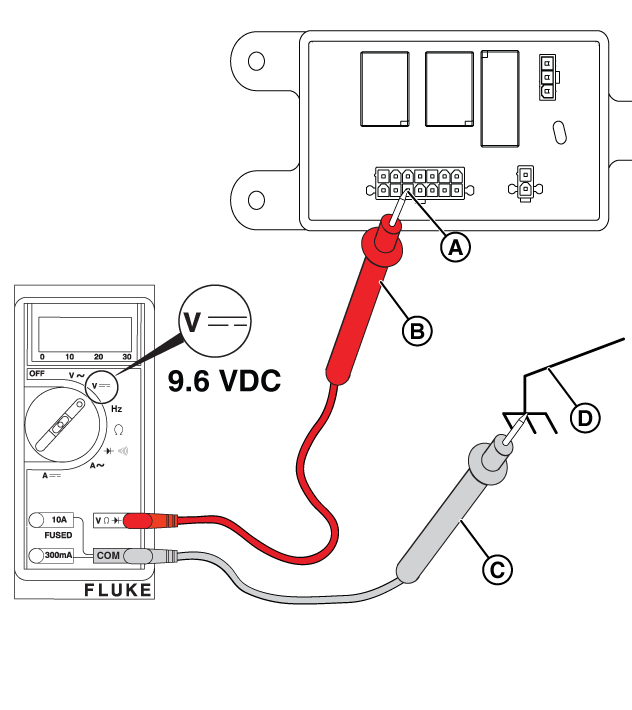
Figure 39
NOTICE: When the fuel solenoid is energized (open) with battery voltage, the applied pressure allows fuel to pass through the fuel pressure regulator. Do not use compressed air, as the fuel pressure regulator diaphragm is easily ruptured.
Figure 40
Potential Cause: Clogged Air Filter, Bad Engine Spark Plugs and/or Plug Wires, Engine Valve Adjustment needed
ALARM(S): Fail to Start
Removal
Figure 92
Installation
NOTICE - Always pull on the boot at the terminal end of the cable. Pulling on the cable can result in damage.
WARNING - Be sure there is no fuel or fuel vapors present, which, if spark-ignited, can cause a fire or explosion resulting in death or serious injury.
NOTICE - The vacuum gauge must fit tightly. On 12-13 kW units, the dipstick tube also serves as the oil fill neck, so wrap the vacuum gauge tube with paper towels as needed to achieve a tight fit.
NOTICE - If necessary, call Briggs & Stratton Technical Support for assistance.
NOTICE - For the best results, check valve clearance when the engine is cold.
When utility is lost a Briggs & Stratton standby generator attempts to start six, (6) times. Scenarios where the generator starts and then shuts down can be caused by various factors, including fuel problems, oil issues, or generator output voltage. Basic preliminary checks, such as confirming fuel pressure, latest controller firmware and settings, or battery voltage/condition, can help rule out basic troubleshooting items.
If all preliminary checks are good, follow the guidance in the Initial Test: Check Generator Output Voltage section below.
NOTICE - Whenever "Test again" appears, install the 15 amp fuse (see your generator's installation and operator's manual for the fuse location), if removed. From MANUAL mode (Engine Off-Ready), press START/SELECT on the controller to check if the engine cranks. If the test fails, remove the 15 amp fuse and proceed to the next step.
If a test passes, follow the linear steps to the appropriate section.
(insert image of Controller with Voltage information)
NOTICE - General images are shown and may not match your unit. Load side voltage testing may be done on the LOAD side of the breaker or a pre-wired terminal block.
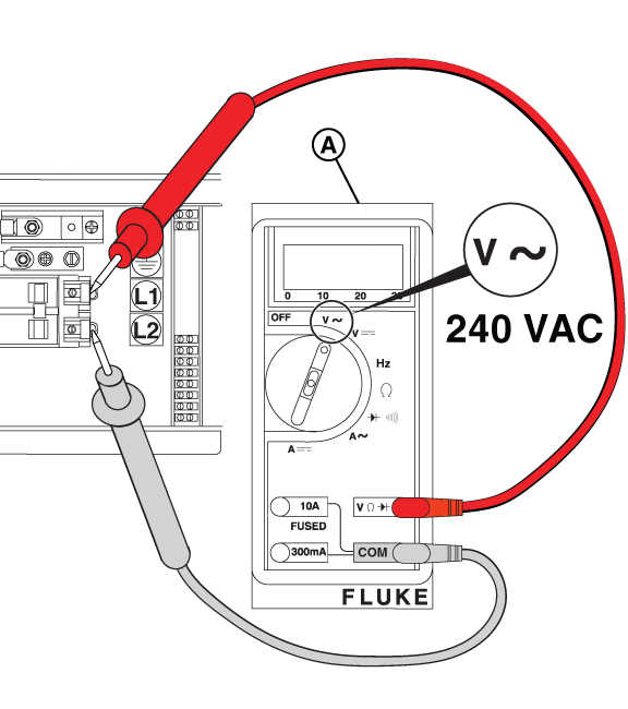
Figure 41
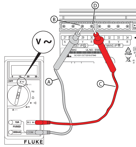
Figure 42
NOTICE - General images are shown and may not match your unit. Line side voltage testing may be done on the LINE side of the breaker or a pre-wired terminal block.
Figure 43
Potential Cause(s): Undersized fuel line (from source to generator)
ALARM(S): Fail to Start + Under Voltage/ Under Speed, or Low Frequency
See Generator Does Not Produce Start section
Potential Cause(s): AVR has incorrect firmware, after replacing AVR
ALARM(S): AVR Fault, Low Voltage (Warning or Failure)
Refer to applicable Service Bulletin and AVR Firmware sections below
Potential Cause(s): Generator produces low voltage (70-120 VAC); Generator produces high voltage (>132 VAC per leg, or >240 VAC)
ALARM(S): AVR Fault, Low Voltage (Warning or Failure); Fail to Start + Over Speed/ Frequency, High Voltage Failure
Removal
Installation
NOTICE - Always hold the AVR by the outside edges only. Avoid touching components, as electro static discharges can damage circuits and sensitive electronic components.
Figure 78
Potential Cause(s): Generator Overspeed or Underspeed
ALARM(S): Fail to Start + Over Speed/ Frequency, High Voltage Failure
See the instructions above, found in the Measure Circuit Breaker Load-Side Voltage section.
See the Check Frequency steps, found in the Generator Does Not Produce Voltage > Symptom: Improper Frequency, or Electronic Governor issues section.
Potential Cause(s): Diode on back of AVR has blown (D12)
ALARM(S): Speed Sensor I/P Lost
Potential Cause(s): No Engine Oil, or Level is too Low; Low Oil Pressure (shorted wire, and/or open switch when running)
ALARM(S): Low Oil Pressure Switch
NOTICE - The normally closed contacts of the switch are held open by engine oil pressure when the engine is running. If oil pressure drops below 7-10 psi, the contacts close to complete a circuit to ground on Wire 85, and the engine shuts down.
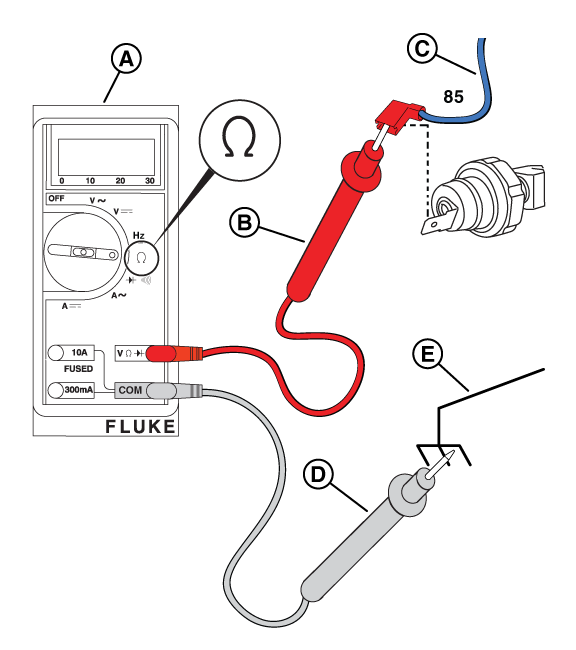
Figure 60
NOTICE - The switch may be tested using a hand or vacuum pump (Briggs & Stratton part number: 19493) or equivalent, applying either vacuum or pressure.
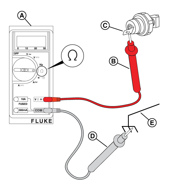
Figure 61
NOTICE - If necessary, call Briggs & Stratton Technical Support for assistance.
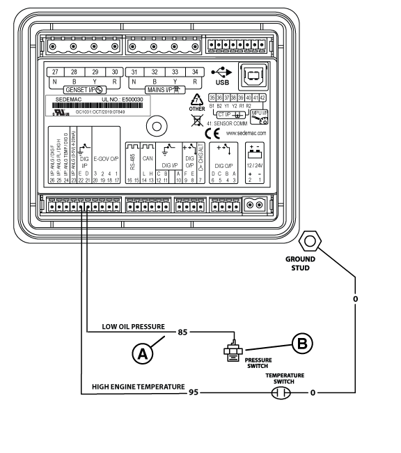
Figure 62
Potential Cause(s): Engine Oil Level is too High; High Engine Temperature Switch (component) = Short to Ground
ALARM(S): High Engine Temperature Switch
NOTICE - The switch contacts are normally open. If the engine temperature goes above 300°F, +/- 7°F (149°C, +/- 4°C), the contacts close to complete a circuit to ground on Wire 95 and the engine will shut down.
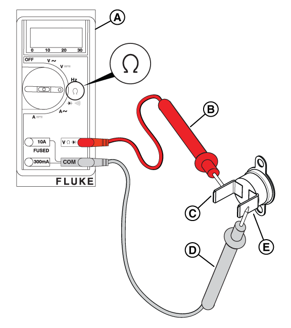
Figure 63
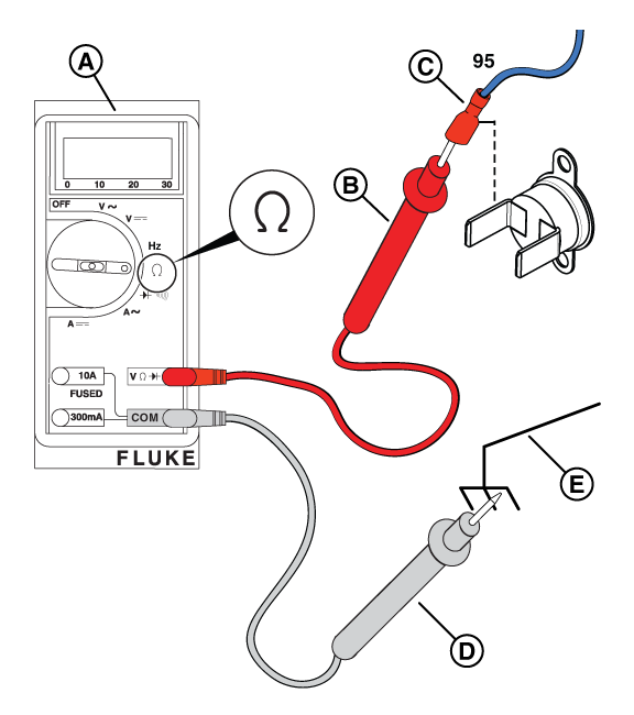
Figure 64
Potential Cause(s): Engine foam seal is deteriorated and recirculating warm engine air
ALARM(S): High Engine Temperature
Potential Cause(s): Air intake is blocked/ obstructed
ALARM(S): Fail to Start + Low Voltage Failure, Under Speed/ Frequency
Potential Cause(s): Improperly sized generator for load demand, or Insufficient fuel pressure
ALARM(S): Over Current/ Load, or Unbalanced Load
Understanding the way the National Electrical Code looks at the home (specifically NFPA 70 Section 220 Service Load Calculations) is the first step to confirm a generator is sized properly for a dwelling. Follow the basic steps below to confirm fuel pressure is sufficient, and the installed generator is sized correctly for the demand/ amp load.
An increase in demand can occur when homeowners add higher amperage load items after a generator is installed. Visit the Briggs & Stratton Power Academy and complete one of the “Residential Sizing and Power Management” courses to learn more about Briggs & Stratton Symphony Power Management System, and proper generator sizing to help homeowners understand what options are available to correct this type of overload or unbalanced load scenario.
Occasionally the engine in a standby generator may audibly “pop” or “sputter” when servicing or manually operating without load on the unit. For instances when an issue may be present, perform basic fuel and output voltage checks before troubleshooting the engine.
NOTICE - Whenever "Test again" appears, install the 15 amp fuse (see your generator's installation and operator's manual for the fuse location), if removed. From MANUAL mode (Engine Off-Ready), press START/SELECT on the controller to check if the engine cranks. If the test fails, remove the 15 amp fuse and proceed to the next step.
If a test passes, follow the linear steps to the appropriate section.
Review the tests found in the Generator Does Not Start and/or Generator Starts and then Shuts Down sections to confirm sufficient fuel is provided to the standby generator.
Review the tests found in the Generator Starts and then Shuts Down and/or Generator Does Not Produce Voltage sections to confirm proper output voltage.
Potential Cause: Faulty spark plugs/ wiring
NOTICE - Pull on the boot at the terminal end of the cable. Do not pull on the cable, as it can cause damage.
WARNING - Make sure there is no fuel or fuel vapors present, which, if spark ignited, can cause a fire or explosion resulting in death or serious injury.
NOTICE - Keep wires away from hot or moving engine parts.
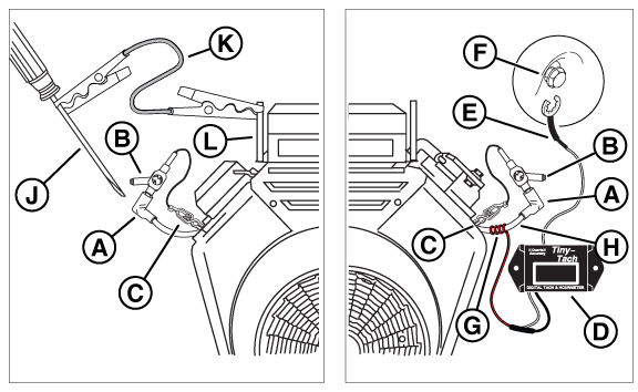
Figure 65
NOTICE - There should not be more than a 75-RPM difference between each cylinder.
NOTICE - If necessary, call Briggs & Stratton Technical Support for assistance.
NOTICE - The vacuum gauge tube must fit tightly. On 12-13 kW units, the dipstick tube is also the oil fill neck, so wrap the vacuum gauge tube with paper towels as needed to achieve a tight fit.
NOTICE - If necessary, call Briggs & Stratton Technical Support for assistance.
When troubleshooting voltage issues on a standby generator, there are a number of electronic circuits and connections to verify. This section includes an order of things to confirm at the basic level, before progressing to complex resistance checks at the Alternator.
NOTICE - Whenever "Test again" appears, install the 15 amp fuse (see your generator's installation and operator's manual for the fuse location), if removed. From MANUAL mode (Engine Off-Ready), press START/SELECT on the controller to check if the engine cranks. If the test fails, remove the 15 amp fuse and proceed to the next step.
If a test passes, follow the linear steps to the appropriate section.
Potential Cause(s): CANBUS Wire issue between AVR and GC-1030 Controller, No/ Low Generator Output Voltage (at Circuit Breaker and/or Controller), Wire harness problem
ALARM(S): AVR Fault, Low Voltage (Warning or Failure)
NOTICE - General images are shown and may not match your unit. Load side voltage testing may be done on the LOAD side of the breaker or a pre-wired terminal block.
Figure 41
Figure 42
NOTICE - General images are shown and may not match your unit. Line side voltage testing may be done on the LINE side of the breaker or a pre-wired terminal block.
Figure 43
NOTICE - 12VDC from the crank circuit is applied to terminal 56 on the Smart AVR. That 12VDC is sent through the AVR and out to the positive brush lead #4.
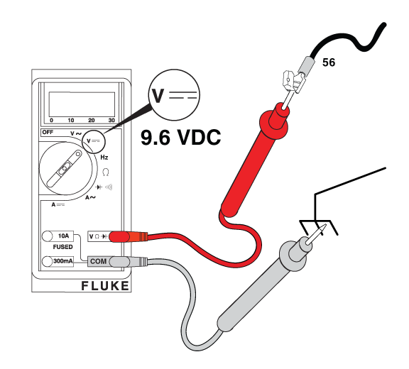
Figure - Field Flash
NOTICE - General images are shown and may not match your unit. Locate the appropriate locations for each of the wires listed. Additional panels may need to be removed.
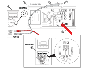
Figure 44
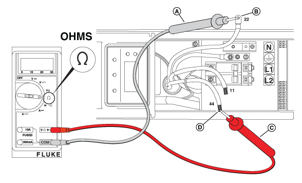
Figure 45
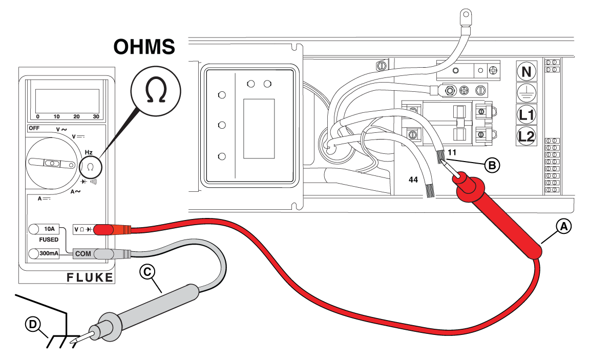
Figure 46
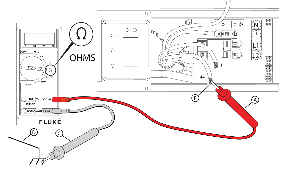
Figure 47
NOTICE - General images are shown and may not match your unit. Locate the appropriate locations for each of the wires listed. Additional panels may need to be removed.
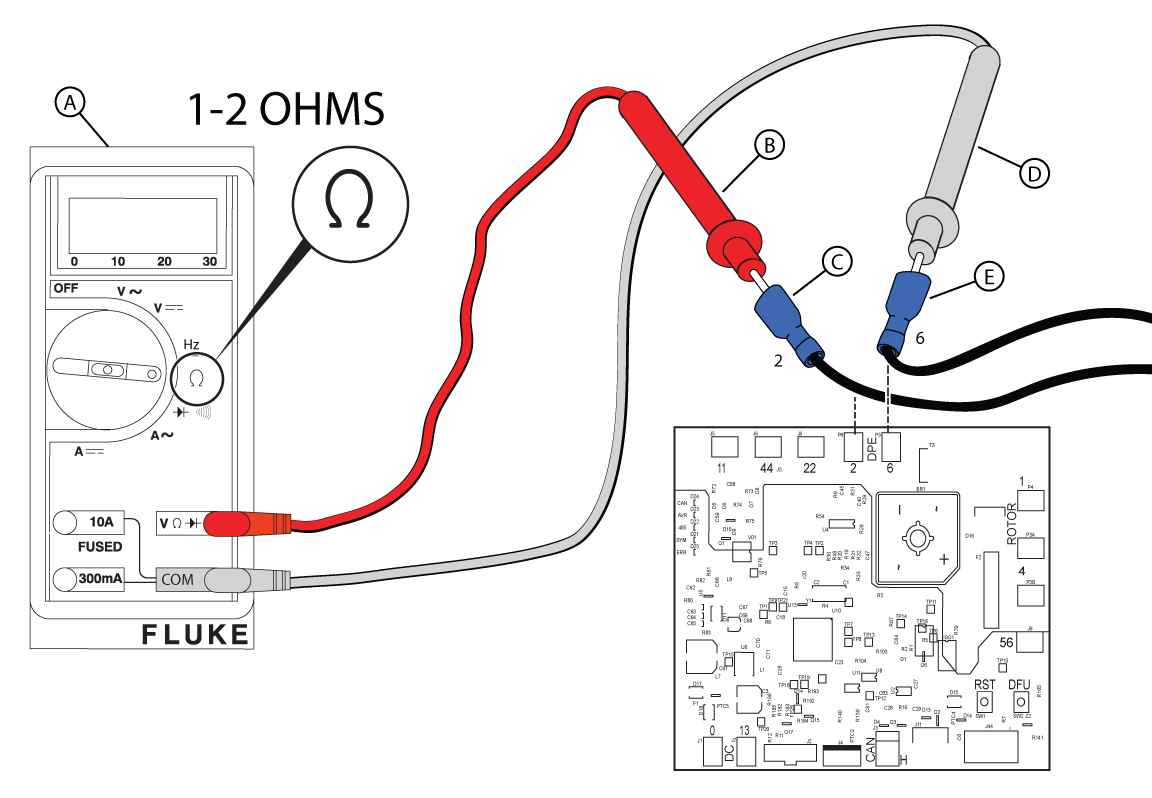
Figure 48

Figure 49
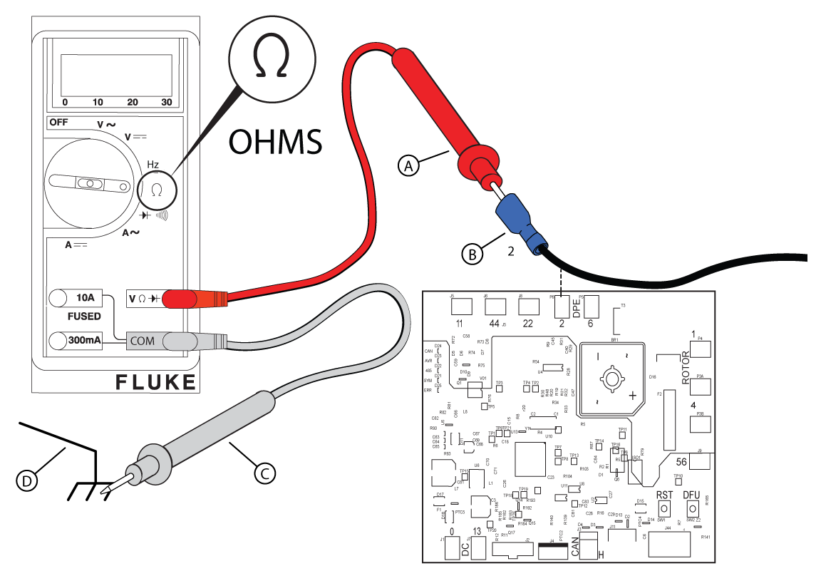
Figure 50
If the previous tests within Check Alternator Rotor Winding Resistance have been completed and the resistance test results are still inconclusive, a megohmmeter (or Megger) test may be necessary.
NOTICE - If you do not have a Megger, go to Check Rotor Resistance Through Brush Wires.
NOTICE - Prior to conducting the megohmmeter test, disconnect all stator leads and the controller and AVR wires.
NOTICE - A reading of 0.5 megohm (500 kOhms) or higher indicates a functional stator.
NOTICE - The rotor resistance can be measured through the brush wires (Wire 1 and Wire 4). This eliminates the need for further disassembly, but can result in a reading that is slightly higher than the specification. See Check DC Amperage in Perform AVR Bypass if the measurement is not within 10% of specification.
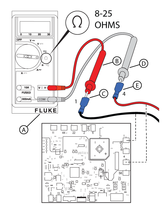
Figure 51
NOTICE - Refer to the Alternator Resistance Chart for exact resistance values for your generator unit.
| Alternator Resistance Chart | |||
|---|---|---|---|
| HSB Power Node | Winding Resistance (ohms) | ||
| Rotor | Stator (Power WIndings) | Stator (DPE) | |
| 12kW | Wires (+) - (-): 11.767 - 14.381 | Wires 11-44: 0.144 - 0.176 | Wires Z1-Z2: 0.387 - 0.473 |
| 13kW | Wires (+) - (-): 11.767 - 14.381 | Wires 11-44: 0.144 - 0.176 | Wires Z1-Z2: 0.387 - 0.473 |
| 17kW | Wires 1-4: 16.2 - 23.5 | Wires 11-44: 0.10 - 0.12 | Wires 2-6: 0.77 - 0.94 |
| 18kW | Wires 1-4: 9.43 - 10.09 | Wires 11-44: 0.106 - 0.109 | Wires 2-6: 0.932 - 0.947 |
| 20kW | Wires 1-4: 16.2 - 23.5 | Wires 11-44: 0.10 - 0.12 | Wires 2-6: 0.77 - 0.94 |
| 22kW | Wires 1-4: 9.43 - 10.09 | Wires 11-44: 0.106 - 0.109 | Wires 2-6: 0.932 - 0.947 |
| 26kW | Wires 1-4: 11.01 - 12.05 | Wires 11-44: 0.065 - 0.075 | Wires 2-6: 0.946 - 0.97 |
NOTICE - Refer to the Alternator Resistance Chart for exact resistance values for your generator unit.
NOTICE - Under certain loading conditions, oxide or brush deposits can accumulate on slip rings causing an increase in electrical resistance. If resistance is high, remove the brushes and clean the slip rings with an applicable surface-conditioning product, such as a 3M Scotch-Brite Hand Pad. Do not use sandpaper or an emery cloth, as abrasive particles will embed in the slip rings and brushes.
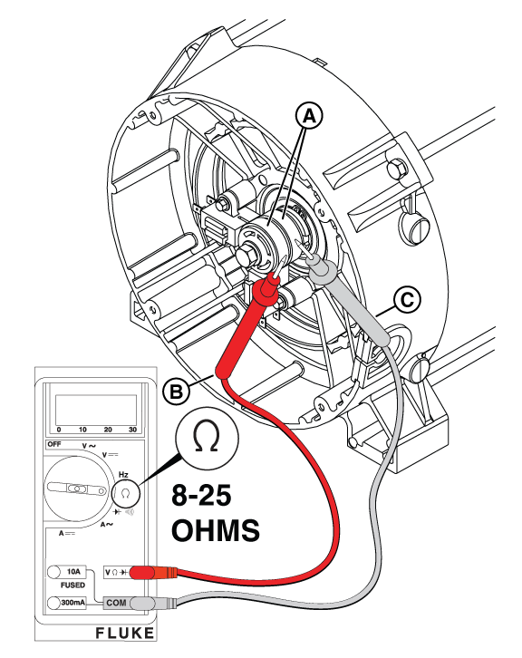
Figure 52
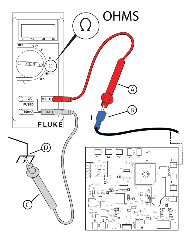
Figure 53
NOTICE - If you bypass the AVR, all wiring and windings in the alternator can be tested without more disassembly. The tests require a fully charged 12V battery. If the battery is not fully charged, it will cause inaccurate readings that can result in a false diagnosis.
NOTICE - You must identify wires by number stamp, not color. Negative leads can be red and positive leads can be black.
NOTICE - To protect AVR terminals from damage and make sure that a fast and easy diagnosis is done, make a test harness (with an in-line fuse on the positive side).
NOTICE Installing a 5 amp in-line fuse on the jumper wire between the battery and Wire 4 is recommended.
WARNING - Utility Voltage is present at the controller. Avoid contact with any bare wires. Use caution to avoid personal injury and/or equipment damage.
| Wires 2 and 6 | |||
|---|---|---|---|
| AC Voltage | Zero | < 100 | ≥ 100 |
| NOTE: The left carrot symbol (<) means "less than" and the underlined right carrot symbol (≥) means "equal to or greater than". | |||

Figure 54
| Wires 11 and 44A | |||
|---|---|---|---|
| AC Voltage | Zero | < 120 | ≥ 120 |
| NOTE: The left carrot symbol (<) means "less than" and the underlined right carrot symbol (≥) means "equal to or greater than". | |||
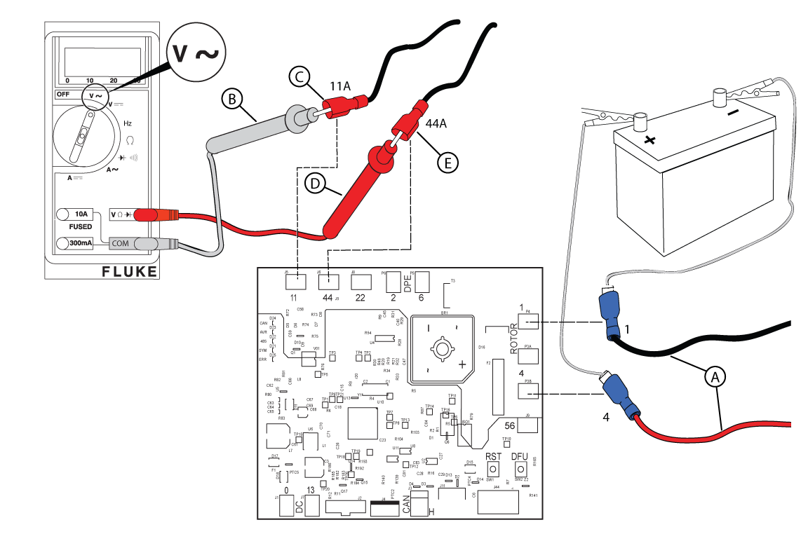
Figure 55
NOTICE - The Check DC Amperage test should only be conducted if BOTH the power and excitation winding tests fail to meet specifications. If the power and winding excitation winding tests show acceptable results, there is no need to conduct DC amperage testing.
NOTICE - The exact amperage readings may vary depending on ambient temperature, battery voltage, meter calibration, etc.
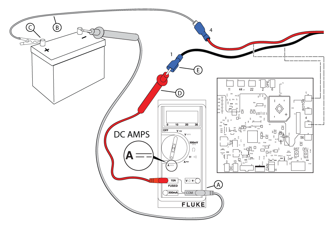
Figure 56
NOTICE - For accurate results, make sure the wire is in the center of the meter.
NOTICE - Current, measured in amperes, in a circuit can be calculated by using Ohm's Law. Voltage divided by resistance (ohms) equals current (amps). The equation is I = V/R. For example, if the voltage (V) of a circuit equals 12 volts and the resistance in ohms (R) equals 12 ohms, then by using the equation, there is 1 amp (I) (12V/12R = 1I).
NOTICE - Normal readings are 1.0-1.5 amps (12-13 kW) or 0.6-0.75 amps (17-26 kW).
| DC Amperage | ||||
|---|---|---|---|---|
| 12-13 kW Unit | Zero | Low | 1.0 - 1.5 | High |
| 17-26 kW Unit | Zero | Low | 0.6 - 0.75 | High |
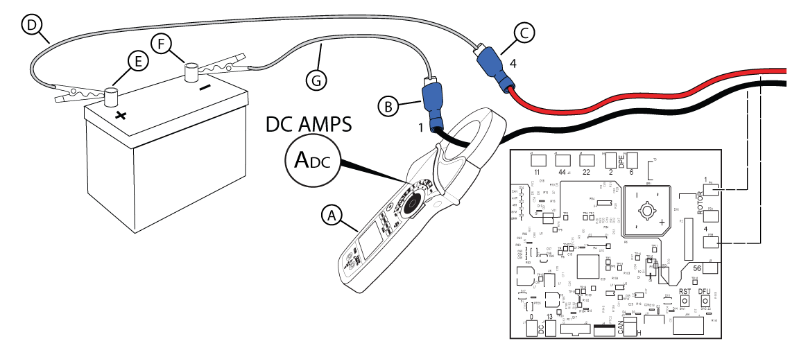
Figure 57
NOTICE - Contact Briggs & Stratton Technical Support to receive prior authorization before installing a new rotor or stator.
NOTICE - It may be necessary, but not required, to replace the AVR when a new stator is installed.
NOTICE - < is "less than"; > is greater than"; ≥ is "greater than or equal to".
| Smart AVR | |||||||||||
|---|---|---|---|---|---|---|---|---|---|---|---|
| DC Amperage | A | B | C | D | E | F | G | ||||
| Wires 2 and 6 | ≥ 100 | ≥ 100 | < 100 | Zero | < 100 | < 100 | High | ||||
| Wires 11A and 44A | ≥ 120 | < 120 | ≥ 120 | Zero | < 120 | < 120 | < 120 | ||||
| DC Amperage (12-13kW | 17-26kW) |
1.0-1.5 | 0.6-0.75 | 1.0-1.5 | 0.6-0.75 | 1.0-1.5 | 0.6-0.75 | Zero or Low | High | 1.0-1.5 | 0.6-0.75 | Zero |
| Replace | AVR | Stator | Stator | Rotor | Rotor | Stator | Rotor or Stator | ||||
NOTICE - If you reach this point of the diagnostics twice, call Briggs & Stratton Technical Support for further instructions.
Potential Cause(s): Generator Overspeed or Underspeed
ALARM(S): Fail to Start Alarm + Over Speed/ Frequency, High Voltage Failure
Action: (refer to applicable Service Bulletin and AVR Firmware sections below)
NOTICE - General images are shown and may not match your unit.\
NOTICE - 180 Hz is not possible. Check the meter or use a tiny tachometer to check engine RPMs.
Figure 58
NOTICE - Keep wires away from hot or moving engine parts.
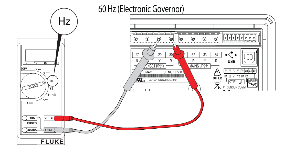
Figure 59
NOTICE - If necessary, call Briggs & Stratton Technical Support for assistance.
NOTICE - Whenever "Test again" appears, install the 15 amp fuse (see your generator's installation and operator's manual for the fuse location), if removed. From MANUAL mode (Engine Off-Ready), press START/SELECT on the controller to check if the engine cranks. If the test fails, remove the 15 amp fuse and proceed to the next step.
If a test passes, review the full linear logic steps found in the Service Call & Maintenance Best Practices section.
Potential Cause(s): Missing or faulty wires from fuse block in ATS, to Terminals 25 and 26 at the Generator; Utility ‘Sense’ fuses have blown in ATS
ALARM(S): N/A
Figure 15
NOTICE - Before replacing the fuses, turn off utility power and remove the fuses from the fuse holder and verify that no continuity to ground is present. If continuity to ground is present, check for wire shorts or a failed battery charger, warmer, or controller.
Figure 16
Nearly 30 different Alarms are programmed on the Generator Controller. The standby generator includes sensors that automatically stop the generator in potentially damaging conditions.
Potential Root Cause(s):
Jumper is removed from generator Terminals 11 and 12, Wires 100A and/or 100B are removed from Terminals 11 and 12 and/or the relay board (E-Stop Terminals 1 and 2), Wire 100C is obstructed between relay board Terminal 3 (E-Stop) and controller Terminal 25 (Pin 9, I/P: ANLG FL/DIG H).
The GC-1030 Series Controller will store up to 100 events in an event log.
NOTICE - Fuel is only present on units with a liquid propane (LP) supply tank.
Figure 3
| 12-13kW NG and LP Configurations | |||||
|---|---|---|---|---|---|
| Model | Engine | Frequency | Fuel Type | Main Jet Turns | Idle Jet Turns |
| 12kW | BSPP 38 v/s | 60 Hz | NG | 1/2 | 2-1/2 |
| LP | 0 | 1/4 | |||
| 13kW | BSPP 38 v/s | 60 Hz | NG | 1-3/8 | 3/8 |
| LP | 1/8 | 3/4 | |||
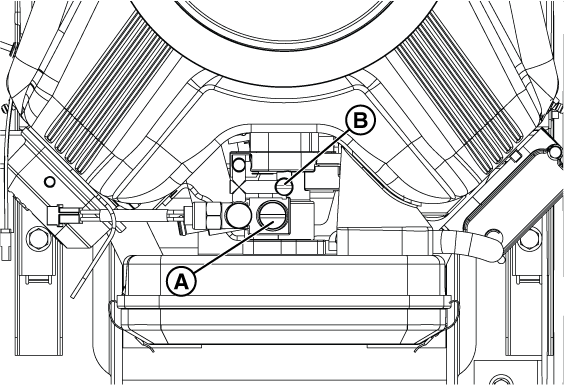
Figure 4
NOTICE - If you are changing the setup in the generator's controller from the factory setting of NG fuel to LP fuel you will need to enter the configuration menu by using the Dealer Password, which is available on the Power Portal.
NOTICE - Selecting a profile that is not intended for the generator can cause the generator to run erratically and can result in damage.
<
Figure 5
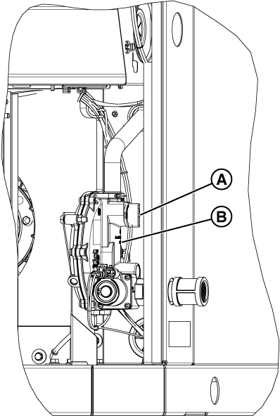
Figure 7
Figure 8
Figure 9
NOTICE - If you are changing the setup in the generator's controller from the factory setting of NG fuel to LP fuel you will need to enter the configuration menu by using the Dealer Password, which is available on the Power Portal.
NOTICE - Selecting a profile that is not intended for the generator can cause the generator to run erratically and could result in damage.
NOTICE - The generator inlet fuel pressure should be 11-14 inches WC (LP) or 3.5-7 inches WC (NG).
NOTICE - If a test port does not exist, see the appropriate installation manual for instructions on installing it. To proceed with troubleshooting in the absence of a test port, go to step 4 of Check Fuel Solenoid and Thermal Fuses to use the test port in the fuel pressure regulator (B, Figure 32). Although use of this port will indicate whether fuel is present, it will not indicate whether the incoming fuel has dropped in pressure.
NOTICE - No more than 0.5 inches WC drop should be seen between static and dynamic fuel pressure and the fuel reading should be stable.
Figure 32
These are some of the most common reasons a generator may fail to crank, start, or run. Complete each of the following tests before you go to Using Linear Diagnostics.
Steps for each of these checks can be found in the Confirm Basic System Set-up (Preliminary Checks) section.
After inspecting and clearing any faults on the GC-1030 Series Controller, the following linear diagnostics methodology can be used to help you determine where the specific problem lies.
This will determine the actual point at which to begin the diagnosis. Since it is possible that certain actions can have unexpected consequences, always return to “Does the engine crank?” after troubleshooting and performing any repair. Even if you are confident that a particular problem was corrected, continue to the very end of the diagnostics (Section 5: Check Switches) to be sure that other problems do not exist.
NOTICE - Verify that the 15 amp fuse is installed in the controller. Press and hold START/SELECT on the controller to crank and start the engine.
NOTICE - Make sure the controller is powered on and the PMD is in the ON position.
After inspecting and clearing any controller faults, proceed as follows:
Tests include load testing the battery and confirming battery connections, verifying utility voltage input to the battery charger, and sufficient trickle charge (confirming battery charger is operational). Additional tests include confirming the starter relay signal and starter solenoid connection, and proper output at the Generator Controller and Relay Board components.
Review the “Generator Does Not Start” section for basic troubleshooting steps.
Tests include confirming fuel items, such as checking fuel supply pressure, fuel solenoid and thermal fuses, and fuel pressure regulator option. The engine may exhibit failure to turn over fast enough. Additional verification tests include engine items, such as checking spark, crankcase vacuum, and/or checking and adjusting valve clearance.
Review the “Generator Does Not Start” section for basic troubleshooting steps.
Tests include measuring generator voltage at the LOAD side of the circuit breaker, the control panel, and LINE side of the circuit breaker. Instructions for checking the winding resistance (Rotor, Stator, and Power Windings) and additional alternator tests, as well as performing an AVR Bypass Test (checking AC voltage and DC amperage) are also included in this section.
Review either the “Generator Starts and then Shuts Down” or “Generator Does Not Produce Voltage” sections for basic troubleshooting steps.
Run the engine and observe its performance. If the engine runs smoothly perform the check cylinder balance and crankcase vacuum tests. Additional troubleshooting instructions can be found in the appropriate Engine Service Manual for engines that perform poorly.
Review the “Generator Runs Rough” section for basic troubleshooting steps.
Technicians are provided with questions to check and confirm the state of the standby generator, organized by Battery, Fuel, Electrical Controls, Physical, Security, and Load Test.
Additional general information that technicians should note include Equipment (Generator and Transfer Switch), Owner, and Service information.
The Briggs & Stratton Technical Support team is available by phone or email, Monday-Friday, from 7:30 AM - 4:30 PM Central (CST).
When diagnosing a standby generator issue, be sure to utilize all resources available to you, including the Troubleshooting Worksheet and/or Electrical Troubleshooting and Repair Manual. Once you have exhausted all options and resources internal to your company, Briggs & Stratton Technical Support is available to assist.
Technical Support Specialists will ask for the following unit information:
Throughout the year, especially during Hurricane/ Storm Season, wait times may increase. Technical Support provides a call back option where your spot in line is reserved, and an agent will call you back when they are available.
As of February 2025, new hold messages have been introduced assisting you with basic troubleshooting steps and product reminders. Please let us know if they
For standby generators within their standard warranty period requiring major repair (e.g. engine, alternator, or (blank) replacement), a control authorization number may be required. Additional items requiring authorization may include, but are not limited to additional repair time, mileage, and/or site trip charge(s).
Technical support documents are available to assist you when troubleshooting an air-cooled standby generator.
This manual provides a comprehensive linear path to correctly diagnose most generator problems, including those units with a GC-1030 Series Controller.
Before you start the diagnosis, answer the questions listed in the Introduction and Preliminary Checks sections before proceeding to the Using Linear Diagnostics section. This will determine the actual point at which to begin the diagnosis.
Illustrations and detailed instructions for removing and installing various standby generator components are included, organized in sections for the 12-13kW vertical and 17-26kW horizontal units.
040740
PowerProtect 13kW (PP13)
View Parts Manual
040746
PowerProtect 13kW (PPDX13)
View Parts Manual
040756
PowerProtect 18kW (PP18)
View Parts Manual
040786
PowerProtect 22kW (PP22)
View Parts Manual
040780
PowerProtect 22kW (PPDX22)
View Parts Manual
040806
PowerProtect 26kW (PP26)
View Parts Manual
040800
PowerProtect 26kW (PPDX26)
View Parts Manual
Specific technical documentation may be available, in the form of a Service Bulletin. These items detail a condition on the standby generator and/or engine, as well as corrective action steps.
Multiple different types of Service Bulletins may apply to a particular standby generator model.
NOTE: A PowerPortal login is required to view Briggs & Stratton Service Bulletin documentation.
Always reference any applicable Service Bulletin documentation when conducting maintenance or service at a customer's location.
PowerProtect 13kW (040740 and 040746; Vertical Unit)
PowerProtect 18kW (040756; Horizontal Unit)
DSB1153
Any GC-1032 Controller service part that is manufactured AFTER January 01, 2024 will no longer have the firmware loaded. The data label located on the back of the GC-1032R controller will display the manufacturing date. Consult the documentation to upload the appropriate firmware version to the GC-1032 Controller, using the SmartFlash tool.
View Document
DSB1163
Air-cooled standby generators having R4.00, R4.01, or R4.02 firmware versions installed on the GC-1032 Controller may exhibit performance issues (e.g. exercise cycle does not execute properly). Consult the documentation to upload the appropriate firmware version to the GC-1032 Controller, using the SmartFlash tool.
View Document
PowerProtect 22 & 26kW (040780, 040786, 040800, 040806; Horizontal Units)
This section includes Instructions on how to install and use the software and firmware for use on Briggs & Stratton PowerProtect standby generators.
Qualified service technicians must use the Firmware Programmer software to program the Smart AVR.
Firmware Programmer - Hardware/Software Requirements
NOTE: The same Firmware Programmer v1.1 software used for programming the Briggs & Stratton Standard Controller may also be used to program and verify programming on the Smart AVR.
Qualified service technicians must use the Smart Flash software to program the GC-1030 Series GENSET Controller.
Smart Flash - Hardware/Software Requirements
SmartFlash Software Security Code
To use the SmartFlash software, users will be prompted to enter a Security Code (1031). This will only be requested once, after installing/re-installing the software application.
Documentation
Instructions for programming the GC-1032R Controller can be found at the link below.
NOTE: Similar steps may be followed when programming a GC-1031 or GC-1032 Controller (selecting a specific generator from the software is not available).
The following recommended and speciality tools may be necessary for servicing this standby generator.
Engine Parts
Cold Weather Kit
Generator Parts
Engine Parts
Cold Weather Kit
Generator Parts
The Briggs & Stratton Power Academy is a virtual learning hub offering various types of training options for selling, installing and servicing energy solutions products. Self-paced eLearning, live virtual and in-person courses are offered to fit your schedule and learning style. Use the button below to sign up for a new account, or login to access training classes.
ThePowerPortal.com is a secure, password protected website created in partnerships with our dealers, distributors, suppliers and customers. Access to brand information is available for many of the Briggs & Stratton family product lines, including standby generators.
Simply put, the PowerPortal is the primary online resource for access to product, engine, parts, warranty, educational, and account information.
eParts is a web based system for retrieving information about parts from Briggs & Stratton Energy Solutions. eParts lets you look up a standby generator and an engine model and display an Illustrated Parts List (IPL) of its assemblies.
You can:
Two, (2) different types of user accounts are available on the PowerPortal. The Primary Account Holder (DDM #) account is created when an agreement with Briggs & Stratton is completed, from a Dealer, Distributor or Authorized Installer business. Users with this login can create Technician Accounts that are managed .
Read more about these critical PowerPortal account types here:
A primary account for the PowerPortal was created when you agreed to become an authorized partner with Briggs & Stratton. This is commonly referred to as a DDM account.
Something just as powerful on the PowerPortal is a Technician Account, which is created and managed under the primary account. These accounts are well suited for technicians or salespersons working at your company, needing access to the following items:
NOTE: Technician accounts are NOT able to place orders or file warranties, and ARE empowered to access the tools necessary to support your customers!
If you need assistance logging into the PowerPortal, or creating a technician account, click the button below. You will be asked to supply the primary PowerPortal login ID (DDM #) and phone number contact information, as well as the technician's first and last name and their email address (cannot be the company's main email address).
Contact our standby generator Technical Support team at techsupport@basco.com, or 800-759-2744.
You will be asked to provide the standby generator’s Model and Serial Numbers, and must have a Dealer ID number when calling.