Standby Generators
NOTICE: THE ITEMS IN THIS SECTION ARE TO ONLY BE USED BY QUALIFIED SERVICE PERSONNEL.
Use the information below to help troubleshoot issues with a Briggs & Stratton air-cooled standby generator. This page provides common troubleshooting steps. Use of information provided here is not a substitute for reviewing the manuals and other relevant documents for the product you are servicing. The documents contain safety information to make you aware of hazards and risks associated with the product and how to avoid them. It is important that you read and understand the documents and instructions thoroughly. If you are uncomfortable working with electricity or fuel, please contact a qualified service technician.
Common Troubleshooting Scenarios
Service scenarios may present themselves, including basic symptoms, potential causes, and ‘alarms’ on the GC-1030 Series Controller.
Choose from the following Quick Navigation Buttons to navigate to a specific service scenario:
Additional Resources
Briggs & Stratton Energy Solutions offers technical resources and guidance for other types of installation & maintenance scenarios.
For more in-depth electrical troubleshooting instructions, including important safety and warning information, navigate to the Technical Support Resources section and consult the Electrical Troubleshooting and Repair Manual (Air-Cooled Standby Generator with GC-1030 Series Controller) document.
Choose from the following Quick Navigation Buttons to navigate to these helpful resources:
Generator Does Not Start
Symptom: Engine Does Not Crank
If the engine in a standby generator will not crank, the issue is likely with the start circuit, such as a dead battery, or a faulty starter motor.
NOTICE - Whenever "Test again" appears, install the 15 amp fuse (see your generator's installation and operator's manual for the fuse location), if removed. From MANUAL mode (Engine Off-Ready), press START/SELECT on the controller to check if the engine cranks. If the test fails, remove the 15 amp fuse and proceed to the next step.
If a test passes, follow the linear steps to the appropriate section. If the engine begins to Crank, but does not Start, advance to Symptom: Engine Does Not Start.
Potential Cause: Weak/Failed battery, battery charger, and/or battery connections issue
ALARM(S): Battery Under Voltage, Battery Over Voltage
-
Confirm Fuse & Check 12V Battery Voltage Supply
- Press STOP/CONFIG on the controller.
- Remove the 15 amp fuse from the controller. Is the fuse blown?
- Yes - Install a new 15 amp ATO fuse. Test again.
- No - Go to step 3.
- Inspect the battery for damage (melted posts, discoloration, raised top, warped case, leaks or cracks). Do any conditions exist?
- Yes - Get a new battery. Go to step 6.
- No - Go to step 4.
- Inspect battery for correct installation: verify polarity, clean terminals, inspect clamps/cables, check fluid level (fill with distilled water only if low). Do any conditions exist?
- Yes - Correct conditions as necessary. Go to step 5.
- No - Go to step 5.
- Disable the battery charger.
- Disconnect the battery and check state of charge with a Digital Multimeter set to DC volts. Place red lead on (+) post, black lead on (-) post. Is voltage 9.6 VDC or lower, 10-12 VDC, or 12 VDC or higher?
- 9.6 VDC or lower - Obtain a new battery. Go to step 7.
- 10-12 VDC - Fully charge the battery. Go to step 7.
- 12 VDC or higher - Go to step 7.

Figure 11 - Load test the battery with an approved tester. Does the battery pass?
- Yes (original battery) - Go to step 8.
- Yes (new battery) - Go to Check Utility Voltage Input.
- No - Obtain a new battery. Repeat step 7.
NOTICE - If no battery load tester, refer to Part No. 80114787 for instructions.
- Enable the battery charger.
- Connect battery and install fuse. Turn on PMD. Back probe Pin 1 (-) and Pin 2 (+) on the controller. Is voltage approximately 13.5 VDC with charger on or more than 9.6 VDC without charger?
- Yes - Go to Check Starter Relay Signal.
- No - Go to step 10.
WARNING - Avoid touching both terminals simultaneously. Do not probe pins directly - arcing can damage components and cause eye injury. Wear safety glasses.
WARNING - Fuel and fuel vapors can be ignited, causing explosion resulting in death or serious injury.

Figure 12 - With 2-pin connector plugged into controller, measure DC voltage from Pin 2 to negative battery (-) post. Is voltage approximately 13.5 VDC with charger on or more than 9.6 VDC without charger?
- Yes - Go to step 12.
- No - Go to step 11.

Figure 13 - Inspect all wiring and connections on the controller for damage, loose, or disconnected wires. Do any conditions exist?
- Yes - Repair or replace as necessary. Test again.
- No - Return to step 9.
- Inspect all wires, cables, and connectors in the unit. Pay attention to ground posts and frame grounds. Do any conditions exist?
- Yes - Replace or repair as necessary. Test again.
- No - Go to Check Starter Relay Signal.
-
Check Utility Voltage Input
- Connect battery and install fuse. Turn on PMD. Set Digital Multimeter to AC volts. Measure AC voltage at the utility connector (MAINS I/P Terminals 33 and 34) on controller. Is approximately 240 VAC present?
- Yes - Go to Check Trickle Charge at the Battery.
- No - Go to step 2.

Figure 14 - Measure AC voltage on the bottom side of the two transfer switch fuses. Is approximately 240 VAC present?
- Yes - Repair or replace the wiring between the transfer switch and generator. Test again.
- No - Go to step 3.

Figure 15 - Measure AC voltage on the top side of the two transfer switch fuses. Is approximately 240 VAC present?
- Yes - Remove the fuses and test for continuity. Replace the open fuse(s). Test again. NOTICE - Before replacing fuses, turn off utility power and verify no continuity to ground is present. If continuity to ground is present, check for wire shorts or a failed battery charger, warmer, or controller.
- No - Repair or replace transfer switch wiring. Test again.

Figure 16
- Connect battery and install fuse. Turn on PMD. Set Digital Multimeter to AC volts. Measure AC voltage at the utility connector (MAINS I/P Terminals 33 and 34) on controller. Is approximately 240 VAC present?
-
Check Trickle Charge at the Battery
NOTICE - If a new battery is installed during a utility outage, the charging circuit must be tested after restoration of utility power.
- Set Digital Multimeter to AC volts. Back probe pins L1 and L2 on the battery charger (Wires 16 and 17). Is approximately 240 VAC present?
- Yes - Go to step 2.
- No - Go to Check Utility Voltage Input.

Figure 17 - Set Digital Multimeter to DC volts. Measure DC voltage across the battery terminals (red lead on + post, black lead on - post). Is voltage equal to or greater than 13.0 VDC?
- Yes - Test again.
- No - Go to step 3.

Figure 18 - Set Digital Multimeter to AC volts. Back probe pin 6 (Wire 44B) and pin 14 (Wire 11B) on the relay board. Is approximately 240 VAC present? NOTICE - The relay board on 13 kW units does not have the 3-pin connector shown in following images.
- Yes - Go to step 4.
- No - Repair or replace Wire 44B (pin 6) and/or Wire 11B (pin 14) between the generator and the relay board.

Figure 19 - Back probe pin 5 (Wire 16) and pin 13 (Wire 17) on the relay board. Is approximately 240 VAC present?
- Yes - Go to Check Starter Relay Signal.
- No - Repair or replace Wire 16 (pin 5) and/or Wire 17 (pin 13) between the battery charger and the relay board.

Figure 20
- Set Digital Multimeter to AC volts. Back probe pins L1 and L2 on the battery charger (Wires 16 and 17). Is approximately 240 VAC present?
Potential Cause: Starter Relay/Starter Solenoid component or wiring issue
ALARM(S): Fail to Start
-
Check Starter Relay Signal
- Set Digital Multimeter to DC volts. Remove Wire 56A from starter relay spade contact. Connect positive (+) lead to Wire 56A, connect negative (-) lead to ground.
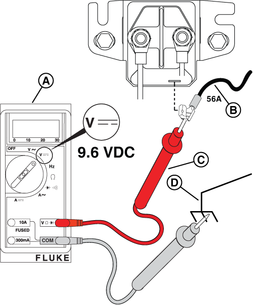
Figure 21 - Install a 15 amp fuse in the controller.
- Turn on the PMD.
- Press START/SELECT on the controller to start the engine.
- Measure DC voltage while the controller sends the crank signal (approx 10 sec ON and 10 sec OFF for two minutes). Is voltage equal to or greater than 9.6 VDC?
- Yes - Alternately check for the same DC voltage at the positive and negative posts of the starter relay while Wire 56A has voltage. Is VDC present on both sides?
- Yes - Go to Check Starter Solenoid Connection.
- No - Install a new starter relay. Test again.
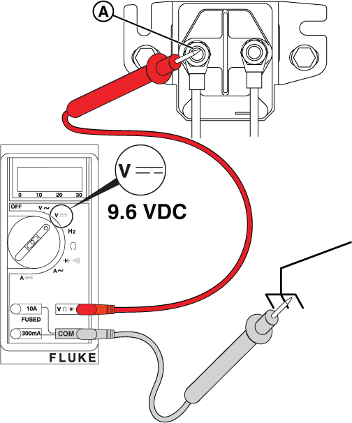
Figure 22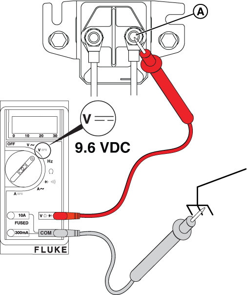
Figure 23 - No - Less than 9.6 VDC - Go to Check Battery Voltage Supply.
- No - No voltage - Go to Check Controller Output.
- Check the ground condition through the base of the solenoid.
- Yes - Alternately check for the same DC voltage at the positive and negative posts of the starter relay while Wire 56A has voltage. Is VDC present on both sides?
- Set Digital Multimeter to DC volts. Remove Wire 56A from starter relay spade contact. Connect positive (+) lead to Wire 56A, connect negative (-) lead to ground.
-
Check Starter Solenoid Connection (13kW Vertical Unit)
- Is the battery voltage at the positive post of the starter relay equal to or greater than 9.6 VDC?
- Yes - Go to step 2.
- No - Repair or replace the wiring and/or connections between the battery and starter relay. Test again.
Figure 24 - Connect the positive (+) meter test lead to the battery cable connection at the starter relay. Connect the negative (-) lead to ground.
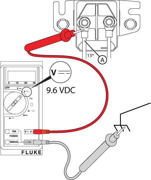
Figure 25 - Press START/SELECT on the controller to crank the engine.
- Is DC voltage equal to or greater than 9.6 VDC?
- Yes - Check that the engine spins freely and is not locked up. If the engine spins freely, install a new starter. Test again.
- No - Repair or replace the main battery wiring between the starter and starter relay. Test again and go to Check Controller Output.
- Is the battery voltage at the positive post of the starter relay equal to or greater than 9.6 VDC?
-
Check Starter Solenoid Connection (18-26kW Horizontal Units)
- Is battery voltage at the positive (+) post of the starter solenoid equal to or greater than 9.6 VDC?
- Yes - Go to step 2.
- No - Refer to the Starter Motor Solenoid Voltage Test section in the engine repair manual (Part No. 80114787). Repair or replace wiring and/or connections.
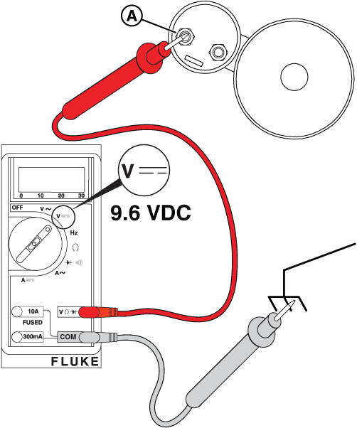
Figure 26 - Is battery voltage on Wire 2 at the starter relay (Wire 97 on some models) equal to or greater than 9.6 VDC?
- Yes - Go to step 3.
- No - Go to Check Battery Voltage Supply.
- Disconnect control wire 1 (Wire 98 on some models) from the spade contact at the starter solenoid. Connect positive (+) lead to the control wire, connect negative (-) lead to ground.
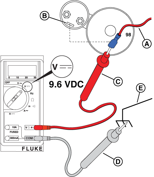
Figure 28 - Install a 15 amp fuse at the controller.
- Turn on the PMD.
- Press START/SELECT on the controller to crank the engine.
- Is DC voltage on the control wire at the starter solenoid equal to or greater than 9.6 VDC?
- Yes - Check that the engine spins freely and is not locked up. If the engine spins freely, install a new starter. Test again.
- No - Repair or replace the wiring between the starter relay and the starter solenoid. Test again and go to Check Controller Output.
- Is battery voltage at the positive (+) post of the starter solenoid equal to or greater than 9.6 VDC?
Potential Cause: Generator Controller or Relay Board does not output 9.6 VDC or greater
ALARM(S): Fail to Start
-
Check Controller Output
At the Controller
- Connect positive (+) lead to Terminal 4 (Dig OP B, Wire 56B). Connect negative (-) lead to Terminal 1 (Wire 0B).

Figure 29 - Turn on the PMD.
- Install a 15 amp fuse at the controller.
- Press START/SELECT on the controller to crank the engine.
- Is DC voltage on Pin 1 and Pin 4 equal to or greater than 9.6 VDC?
- Yes - Go to step 6 to measure voltage into and out of the relay board.
- No - less than 9.6 VDC - Go to Check Battery Voltage Supply.
- No - no voltage - Install a new controller. Test again.
At the Relay Board
- Back probe Pin 9 (Wire 56B) on the relay board with the red lead and connect other lead to ground. Is DC voltage equal to or greater than 9.6 VDC? NOTICE - The relay board on 13 kW units does not have the 3-pin connector shown.
- Yes - Go to step 7.
- No - Repair or replace Wire 56B between the relay board (Pin 9) and the controller. Test again.

Figure 30 - Back probe Pin 8 (Wire 56A) on the relay board with the red lead and connect other lead to ground. Is DC voltage equal to or greater than 9.6 VDC?
- Yes - Go to Symptom: Engine Does Not Start.
- No - Repair or replace Wire 56A between the relay board (Pin 8) and the starter solenoid. Test again.

Figure 31
- Connect positive (+) lead to Terminal 4 (Dig OP B, Wire 56B). Connect negative (-) lead to Terminal 1 (Wire 0B).
Potential Cause: Emergency Stop button pressed, and/or wiring connection issue
ALARM(S): Emergency Stop
-
Check Emergency Stop Button
- Locate and reset the E-Stop switch.
- Acknowledge/Clear Alarm at the Controller.
- Re-test.
-
Check Emergency Stop Wiring
Confirm the green E-Stop jumper wire is installed on terminal block pins 6 and 7.
Potential Cause: Generator Controller in MANUAL/Engine Off mode
ALARM(S): N/A
-
Check STATUS on Controller
- Is the 15 amp ATO type fuse installed in the controller?
- Yes - Go to step 2.
- No - Install the 15 amp ATO type fuse in the controller.
- Is the generator controller set to AUTO?
- Yes - Go to Service Call & Maintenance Best Practices.
- No - Press AUTO/MANUAL on the controller. An LED illuminates to indicate that the system is in AUTO mode.
NOTICE - If a fault is present on the controller, go to GC-1030 Series Controller Alarms & Event Log and review the corresponding fault.
- Is the 15 amp ATO type fuse installed in the controller?
Symptom: Engine Does Not Start
An engine in a standby generator that does not start can be caused by a variety of issues, with fuel problems, electrical problems, and mechanical issues being the most common. Troubleshooting typically involves checking oil and fuel levels, the battery, spark plugs, air filter, and the choke.
Potential Cause: Engine Oil Level is Incorrect/Insufficient (Low or No Oil)
ALARM(S): N/A
-
Preliminary Checks - Engine Oil Level
- Check that the engine has been filled to the correct level with the recommended oil. Is the oil at the correct level?
- Yes - Go to Change Engine Oil and Filter.
- No - Slowly add oil until the correct oil level is reached. DO NOT OVERFILL.
- Check that the engine has been filled to the correct level with the recommended oil. Is the oil at the correct level?
-
Change Engine Oil and Filter
- Use one wrench to hold the hex on the oil drain hose fitting (to prevent rotation), and use a second wrench to remove the drain plug.
- Drain the oil into a suitable container.
- Install the drain plug back into the oil drain hose fitting.
- Rotate the oil filter counter-clockwise to remove it from the oil filter adapter.
- Check that the old gasket is not stuck to the oil filter adapter and that the gasket surface is clean and dry.
- Install a film of clean engine oil to the gasket of a new oil filter.
- Install the oil filter by hand until the gasket contacts the adapter.
- Tighten the oil filter an additional 1/2-3/4 turn.
- Remove the fill cap and fill the engine with the correct quantity and type of oil.
- Quantity (Dry Engine): 12-13 kW (M38): 42-45 oz (1.31-1.41 qt). 17-26 kW (M61): 78-80 oz (2.44-2.5 qt).
- Type: Use only API SJ/CF 5W-30 synthetic oil. DO NOT use special additives.
- Install the fill cap.
- Install the 15 amp fuse in the controller.
- Push and hold START/SELECT on the controller to start the engine.
- Let the engine run for one minute and check for leaks.
- Press OFF on the controller to stop the engine.
- Wait a minimum of five minutes for the engine to cool and for oil to drain back to the oil pan.
- Check the engine oil level: remove the dipstick and wipe dry. Insert fully, wait ten seconds, remove slowly. Check that oil level is at or near the top of the crosshatch pattern on both sides of the dipstick.

Figure 83 - Push and hold START/SELECT on the controller to start the engine. Check for leaks.
- Let the engine run for a minimum of one minute.
- Push and hold STOP/CONFIG on the controller.
- Return to step 15. Repeat until the engine oil level is correct.
- Remove the 15 amp fuse from the controller. NOTICE - Dispose of used oil and the oil filter at a proper waste disposal or recycling center.
Potential Cause: Fuel Pressure is Incorrect/Insufficient (Low or No Fuel)
ALARM(S): Fail to Start
-
Preliminary Checks - Fuel Delivery
- Is sufficient fuel available in the fuel supply tank? NOTICE - Fuel is only present on units with a liquid propane (LP) supply tank.
- Yes - Go to step 2.
- No - Replenish the fuel supply.
- Are the main fuel supply valve and any in-line fuel shutoff valves open?
- Yes - Go to Check Fuel Pressure.
- No - Open the main fuel supply valve and any in-line fuel shutoff valves.
- Is sufficient fuel available in the fuel supply tank? NOTICE - Fuel is only present on units with a liquid propane (LP) supply tank.
-
Preliminary Checks - Fuel Type (12-13kW Vertical Units)
- Remove the roof and front panel.
- For 13 kW units only: press the fuel selector toggle switch (A, Figure 3) on top of the field connection box to the correct position - LP or NG (B).

Figure 3 - Locate the main jet and idle jet on the engine. Jet settings are as follows:
12-13kW NG and LP Configurations Model Engine Frequency Fuel Type Main Jet Turns Idle Jet Turns 12kW BSPP 38 v/s 60 Hz NG 1/2 2-1/2 LP 0 1/4 13kW BSPP 38 v/s 60 Hz NG 1-3/8 3/8 LP 1/8 3/4
Figure 4 - To convert to either fuel: navigate to the SELECT PROFILE page in the controller configuration menu (Dealer Password required to change from NG to LP - available on the Power Portal), press START/SELECT to set the correct profile (e.g. "13KW_LP"), and press and hold STOP/CONFIG to save. NOTICE - For 13 kW Units: DO NOT change the fuel regulator setting - leave at factory NG setting.

Figure 5
-
Preliminary Checks - Fuel Type (17-26kW Horizontal Units)
- Open the roof and remove the air inlet side end cap.
- Locate the fuel selector valve on top of the fuel pressure regulator. To convert fuel types: set the fuel selector lever to LP or NG, select LP or NG on the fuel selector switch, then navigate to the controller configuration menu and set the correct generator profile (e.g. "20KW_LP"). Press and hold STOP/CONFIG to save. NOTICE - Dealer Password required to change from NG to LP. Selecting a profile not intended for the generator can cause erratic operation and damage.

Figure 7
Figure 8
Figure 9
-
Check Fuel Supply Pressure
NOTICE - The generator inlet fuel pressure should be 11-14 inches WC (LP) or 3.5-7 inches WC (NG).
- Close the main fuel supply valve to stop the flow of fuel to the generator.
- Locate the installer-supplied fuel pressure test port closest to the generator. NOTICE - If no test port exists, see the installation manual for instructions. To proceed without a test port, go to step 4 of Check Fuel Solenoid and Thermal Fuses.
- Obtain an analog manometer. Remove the test port plug and install the manometer.
- Open the main fuel supply valve to start the flow of fuel to the generator.
- Inspect the manometer gauge. Is the generator inlet fuel pressure 11-14 inches WC (LP) or 3.5-7 inches WC (NG)?
- Yes - Go to Check Fuel Solenoid and Thermal Fuses.
- No - Repair or replace fuel delivery system. Test again.
NOTICE - No more than 0.5 inches WC drop should be seen between static and dynamic fuel pressure and the fuel reading should be stable.

Figure 32
-
Check Fuel Solenoid and Thermal Fuses
- Locate the fuel solenoid. For 13 and 17-26 kW PowerProtect units, the fuel solenoid is on the fuel regulator assembly.

Figure 33 - Set Digital Multimeter to DC volts. Disconnect the 2-pin connector from the fuel solenoid. Connect positive (+) lead to Wire 14C and negative (-) to ground.

Figure 34
Figure 35 - Measure DC volts at the fuel solenoid while the engine is cranking. Is voltage equal to or greater than 9.6 VDC?
- Yes - Go to step 4.
- No - Go to step 6.
NOTICE - There will not be voltage at the pauses between cranks. When activated, a "click" is heard at the fuel solenoid indicating it opened correctly.
- Set Digital Multimeter to read ohms.
- Measure the pin-to-pin coil resistance on the fuel solenoid. Is the resistance close to 11 ohms?
- Yes - Go to step 6.
- No - Install a new fuel solenoid. Test again.
- Remove the pipe plug from the fuel pressure regulator test port and install an analog manometer.
- Verify that the fuel supply valves are open. NOTICE - Step 8 applies only to Fortress II units. If not a Fortress II unit, skip to step 10.
- Disconnect the 2-pin connector at the fuel solenoid. Connect a jumper wire from the positive battery (+) post to the fuel solenoid.

Figure 36 - Check the manometer gauge: Is fuel pressure 11-14 inches WC (LP) or 3.5-7 inches WC (NG)?
- Yes - Go to step 10.
- No - Low fuel pressure - Repair or replace fuel delivery system. Test again.
- No - No fuel pressure - Install a new fuel solenoid. Test again.
- For PowerProtect units, connect the 2-pin connector at the fuel solenoid.
- Connect positive (+) lead to Terminal 5 (Dig O/P C, Wire 14A) on controller. Connect negative (-) lead to ground.

Figure 37 - Measure DC volts while cranking. Is voltage equal to or greater than 9.6 VDC?
- Yes - Repair or replace Wire 14 between the controller and fuel solenoid. Test again and go to step 13.
- No - Install a new controller. Test again.
- Back probe Pin 11 (Wire 14A) on the relay board. Is DC voltage equal to or greater than 9.6 VDC?
- Yes - Go to step 14.
- No - Repair or replace Wire 14A between relay board (Pin 11) and controller. Test again.

Figure 38 - Back probe Pin 10 (Wire 14B) on the relay board. Is DC voltage equal to or greater than 9.6 VDC?
- Yes - Go to Check Fuel Pressure Regulator.
- No - Repair or replace Wire 14B between relay board (Pin 10) and fuel solenoid. Test again.

Figure 39
- Locate the fuel solenoid. For 13 and 17-26 kW PowerProtect units, the fuel solenoid is on the fuel regulator assembly.
-
Check Fuel Pressure Regulator
- Loosen the bolts holding the regulator to the base.
- Install a barbed 1/8-inch NPT fitting into one of the two atmospheric pressure ports. Attach a 24-inch length of hose to the fitting.
- Install an analog manometer to the fuel pressure regulator test port.
- Disconnect Wire 14C at the 2-pin connector of the fuel solenoid. Connect a jumper wire from the positive battery (+) post to the fuel solenoid.
- Cover the open atmospheric pressure port with your index finger and very gently blow into the hose. Does the manometer show a decrease in pressure?
- Yes - Go to Check Spark.
- No - Install a new fuel pressure regulator. Test again. NOTICE - Do not use compressed air - the fuel pressure regulator diaphragm is easily ruptured.
Figure 40
Potential Cause: Clogged Air Filter, Bad Engine Spark Plugs and/or Plug Wires, Engine Valve Adjustment needed
ALARM(S): Fail to Start
-
Inspect Engine Air Filter
Removal
- Remove the plastic knob or disengage the two retaining clips to release the air filter cover (A, Figure 92).
- Remove thumb nut (B) from threaded rod.
- Remove the metal retainer plate (C).
- Remove and discard the air filter element (D).
- Thoroughly clean the air filter mount (E), metal retainer plate (C), and air filter cover (A) of any dust, dirt, or debris.

Figure 92Installation
- Put a new air filter element (D) onto the air filter mount (E).
- Fit the metal retainer plate (C) evenly and tightly into the air filter element.
- Install the thumb nut (B) onto the threaded rod and tighten.
- Install the air filter cover (A).
- Install the plastic knob or engage the two retaining clips to secure the air filter cover.
-
Check Spark
- Obtain two Ignition Testers (D in Specialty Tools).
- Remove spark plug cables from the spark plug terminals. Always pull on the boot at the terminal end of the cable.
- Install the free end of the spark plug cables onto the tester prongs. Install the tester alligator clips onto the good engine grounds. WARNING - Be sure there is no fuel or fuel vapors present - if spark-ignited, can cause a fire or explosion resulting in death or serious injury.
- Press START/SELECT on the controller to start the engine.
- Is spark present?
- Yes - Ignition is functioning properly. Go to step 6.
- No - Verify the spark tester is properly installed and repeat steps 4-5. If spark is still not present, install a new ignition coil following instructions in the appropriate engine service manual. Test again.
- Press STOP/CONFIG on the controller and remove the 15 amp fuse.
- Remove the tester alligator clips from the engine grounds and install on the spark plug terminals.
- Install a 15 amp fuse and press START/SELECT to start the engine.
- Is spark present?
- Yes - The ignition is operating properly. Go to Check the Crankcase Vacuum.
- No - Go to step 10.
- Fully clean the area around the spark plugs. Remove the spark plugs using a 5/8-inch spark plug socket and check: type (Champion XC92YC or RC12YC), condition (good), and gap (0.020 in for vertical units and 17/20 kW Fortress II, or 0.030 in for 17, 18, 20, 22, 26 kW PowerProtect). Are all conditions observed?
- Yes - Go to Check the Crankcase Vacuum.
- No - Install new spark plug(s). Test again.
-
Check Crankcase Vacuum
- Obtain a digital vacuum gauge.
- Remove the dipstick.
- Insert the vacuum gauge tube into the dipstick tube. NOTICE - On 12-13 kW units, the dipstick tube also serves as the oil fill neck - wrap the vacuum gauge tube with paper towels as needed to achieve a tight fit.
- Press START/SELECT on the controller to start the engine.
- Is the vacuum gauge reading -5 to -10 inches WC?
- Yes - Go to Check and Adjust Valve Clearance.
- No - See the appropriate Engine Service Manual. NOTICE - If necessary, call Briggs & Stratton Technical Support for assistance.
-
Check and Adjust Valve Clearance
NOTICE - For the best results, check valve clearance when the engine is cold.
- Remove the spark plug cables from the spark plug terminals. Always pull on the boot at the terminal end.
- Thoroughly clean the area around spark plugs to keep dirt out of the combustion chamber.
- Remove spark plugs from cylinder heads using a 5/8-inch spark plug socket.
- Turn the engine crankshaft in the direction of engine rotation until the piston of cylinder #1 is at top dead center (TDC) of the compression stroke.
- Insert a TDC tool (or wooden dowel) into the spark plug hole and slowly turn the crankshaft until the piston has moved 0.25 inches (6.0 mm) down the bore past TDC.
- Remove the 4 screws with washers to release the valve cover.
- Insert a feeler gauge between the rocker arm and intake valve stem. Verify intake valve clearance is 0.004-0.006 inches (0.102-0.152 mm).
- If adjustment is necessary: place the 13mm socket over the locknut, insert the 5mm hex or T-40 Torx bit through the hole to engage the adjuster screw, loosen the locknut, adjust the valve clearance, tighten the locknut. Tighten locknut to 70 in-lbs (8 Nm). Recheck clearance.
- Insert the feeler gauge between the rocker arm and exhaust valve stem. Verify exhaust valve clearance is 0.007-0.009 inches (0.178-0.229 mm). If adjustment is necessary, repeat step 8.
- Reinstall valve cover screws alternately to 70 in-lbs (8 Nm) using a crosswise pattern.
- Repeat steps 4-10 on cylinder #2.
- Install spark plugs and tighten to 180 in-lbs (20 Nm). Install spark plug cables.
- Press START/SELECT on the controller. Does the engine start?
- Yes, but engine does not shut off or FAIL TO STOP alarm is present - Go to step 16.
- Yes - Go to Check the Voltage.
- No - Go to Check Fuel Supply Pressure.
- Shut off the fuel supply valve, check that voltage is removed from Wire 14A and Wire 14B, and test for fuel pressure. Is fuel pressure present?
- Yes - Replace the fuel regulator solenoid assembly. Go back to step 13.
- No - Go to Check Fuel Solenoid and Thermal Fuses.
-
Engine Components are Out of Tolerance
Generator Starts and then Shuts Down
When utility is lost a Briggs & Stratton standby generator attempts to start six (6) times. Scenarios where the generator starts and then shuts down can be caused by various factors, including fuel problems, oil issues, or generator output voltage.
If all preliminary checks are good, follow the guidance in the Initial Test: Check Generator Output Voltage section below.
NOTICE - Whenever "Test again" appears, install the 15 amp fuse (see your generator's installation and operator's manual for the fuse location), if removed.
Initial Test: Check Generator Output Voltage
- Press START/SELECT on the controller to start the engine. Does the engine have proper voltage?
- Yes - Depending on how long the generator runs, go to either Symptom: Generator Runs for ONLY 10 Seconds, or Symptom: Generator Runs for LONGER than 10 Seconds, then Shuts Down.
- No - Go to Measure Circuit Breaker Load-Side Voltage.
-
Measure Circuit Breaker Load-Side Voltage
NOTICE - General images are shown and may not match your unit. Load side voltage testing may be done on the LOAD side of the breaker or a pre-wired terminal block.
- Locate the generator circuit breaker and remove the breaker cover plate.
- Verify that the generator circuit breaker is in the ON (Closed) position.
- Install a 15 amp fuse in the controller, if removed.
- Set Digital Multimeter to read AC volts. Press START/SELECT on the controller to start the engine. Is 240 VAC present at the load side of the circuit breaker or terminal block?
- Yes - Go to Measure Generator Voltage at the Controller.
- No - Go to Measure Circuit Breaker Line-Side Voltage.

Figure 41
-
Measure Generator Voltage at the Controller
- With the engine running, back probe Pin 29 (Wire 44C) and Pin 30 (Wire 11C) at the back of the controller. Is 240 VAC present?
- Yes - Install a new controller. Test again.
- No - Repair or replace Wire 44C (Pin 29) and/or Wire 11C (Pin 30). Test again.

Figure 42
- With the engine running, back probe Pin 29 (Wire 44C) and Pin 30 (Wire 11C) at the back of the controller. Is 240 VAC present?
-
Measure Circuit Breaker Line-Side Voltage
NOTICE - General images are shown and may not match your unit. Line side voltage testing may be done on the LINE side of the breaker or a pre-wired terminal block.
- Locate the generator circuit breaker and remove the breaker cover plate (if not already removed).
- Make sure that the generator circuit breaker is in the OFF (Open) position.
- Push START/SELECT on the controller to start the engine. With the engine running, back probe with one meter test lead on the L2 contact and the other on the L1 contact. Is there 240 VAC at the line side of the circuit breaker?
- Yes - Manually cycle the circuit breaker. Test again. If the problem continues, install a new circuit breaker. Test again.
- No - Go to Generator Does Not Produce Voltage.

Figure 43
Symptom: Generator Runs for ONLY 10 Seconds
Potential Cause: Undersized fuel line (from source to generator)
ALARM(S): Fail to Start + Under Voltage/Under Speed, or Low Frequency
-
Check fuel pressure is correct
See Generator Does Not Start section.
Potential Cause: AVR has incorrect firmware, after replacing AVR
ALARM(S): AVR Fault, Low Voltage (Warning or Failure)
-
Confirm AVR firmware matches applicable Service Bulletin
Refer to applicable Service Bulletin and AVR Firmware sections below.
Potential Cause: Generator produces low voltage (70-120 VAC); Generator produces high voltage (greater than 132 VAC per leg, or greater than 240 VAC)
ALARM(S): AVR Fault, Low Voltage (Warning or Failure); Fail to Start + Over Speed/Frequency, High Voltage Failure
-
Verify proper voltage at Load-Side of the Circuit Breaker
See the instructions above, found in the Measure Circuit Breaker Load-Side Voltage section.
-
Replace AVR
Removal
- Locate the AVR (Figure 78) behind the controller.
- Remove the screws to release the generator controller plate.
- Disconnect stator Wires 11A and 11D, Wires 44A and 44D, Wires 22A, 22b, and 22C, and DEP Wires 2 and 6 from the respective terminals on the AVR.
- Disconnect rotor Wires 1 and 4 from the AVR.
- Disconnect the field flash Wire 56C from the AVR.
- Disconnect RS485 8-pin connector J44 from the AVR.
- Disconnect the CAN 2-pin connector Wires 113 and 114 from the AVR.
- Disconnect DC Wires 13D, 13F, 0B, and 0C from the AVR.
- Remove the AVR from the standoffs. Discard in accordance with local codes.
Installation
NOTICE - Always hold the AVR by the outside edges only. Avoid touching components - electrostatic discharges can damage circuits and sensitive electronic components.
- Place a new AVR onto the standoffs.
- Connect stator Wires 11A and 11D, Wires 44A and 44D, Wires 22A, 22b, and 22C, and DEP Wires 2 and 6 to the respective terminals on the AVR.
- Connect rotor Wires 1 and 4 to the AVR.
- Connect the field flash Wire 56C to the AVR.
- Connect RS485 8-pin connector J44 to the AVR.
- Connect CAN 2-pin connector Wires 113 and 114 to the AVR.
- Connect DC Wires 13D, 13F, 0B, and 0C to the AVR.

Figure 78
Potential Cause: Generator Overspeed or Underspeed
ALARM(S): Fail to Start + Over Speed/Frequency, High Voltage Failure
-
Verify proper voltage at Load-Side of the Circuit Breaker
See the instructions above, found in the Measure Circuit Breaker Load-Side Voltage section.
-
Check the Frequency
See the Check Frequency steps, found in the Generator Does Not Produce Voltage > Symptom: Improper Frequency, or Electronic Governor issues section.
Potential Cause: Diode on back of AVR has blown (D12)
ALARM(S): Speed Sensor I/P Lost
-
Replace AVR
See the instructions above, found in the Replace AVR section.
Symptom: Generator Runs for LONGER than 10 Seconds, then Shuts Down
Potential Cause: No Engine Oil, or Level is too Low; Low Oil Pressure (shorted wire, and/or open switch when running)
ALARM(S): Low Oil Pressure Switch
-
Check For Low Oil Pressure
- Press START/SELECT on the controller to start the engine. Let 10 seconds go by so the engine can pressurize. Is a low oil pressure condition indicated?
- Yes - Go to step 2.
- No - Go to Check for High Engine Temperature.
- Is the engine oil level low?
- Yes - Add oil until the level is at or near the top of the crosshatch pattern on the dipstick. Test again.
- No - Go to Check Low Oil Pressure Switch for Short to Ground.
- Press START/SELECT on the controller to start the engine. Let 10 seconds go by so the engine can pressurize. Is a low oil pressure condition indicated?
-
Check Low Oil Pressure Switch for Short to Ground
NOTICE - The normally closed contacts of the switch are held open by engine oil pressure when the engine is running. If oil pressure drops below 7-10 psi, the contacts close to complete a circuit to ground on Wire 85, and the engine shuts down.
- Press START/SELECT on the controller.
- Remove the 15 amp fuse from the controller or turn off the PMD.
- Disconnect Wire 85 from the Low Oil Pressure switch.
- Set Digital Multimeter to read continuity. Measure for short to ground by connecting one meter test lead to Wire 85 and the engine block, and the other to ground. Is short to ground present?
- Yes - Repair or replace wiring. Test again.
- No - Go to Check Low Oil Pressure Switch for Continuity.

Figure 60
-
Check Low Oil Pressure Switch for Continuity
- Disconnect Wire 85 from the Low Oil Pressure switch if installed.
- Install the 15 amp fuse in the controller if removed.
- Press START/SELECT on the controller to start the engine and allow 10 seconds to elapse for the engine to pressurize.
- Set Digital Multimeter to read continuity. Check continuity to ground at the switch spade contact by connecting one meter test lead to the engine block and the other to ground. Is continuity to ground present? NOTICE - The switch may be tested using a hand or vacuum pump (Briggs & Stratton part number: 19493) or equivalent.
- Yes - The switch contacts are closed. Go to Check Engine Oil Pressure.
- No - The switch contacts are open. Install a new controller. Test again.

Figure 61
-
Check Engine Oil Pressure
- Disconnect Wire 85 from the Low Oil Pressure switch.
- Remove the Low Oil Pressure switch and install a suitable oil pressure gauge.
- Install the 15 amp fuse in the controller.
- Press START/SELECT on the controller to start the engine.
- Yes - Install a new Low Oil Pressure switch. Test again.
- No - See the service manual for your engine. NOTICE - If necessary, call Briggs & Stratton Technical Support for assistance.

Figure 62
Potential Cause: Engine Oil Level is too High; High Engine Temperature Switch (component) = Short to Ground
ALARM(S): High Engine Temperature Switch
-
Check for High Engine Temperature
- Install a 15 amp fuse in the controller, if removed.
- Press START/SELECT on the controller to start the engine. Let the engine run for 5 minutes. Is a high engine temperature condition indicated?
- Yes - Go to step 3.
- No - Perform Final Checks.
- Check for these most common causes of high engine temperature: low engine oil level, obstructed air inlet, obstructed exhaust outlet, debris in the engine compartment, deteriorated foam seals, or the roof or side panels are not installed. Are any of these conditions observed?
- Yes - Correct as necessary. Test again.
- No - Go to Check High Engine Temperature Switch for Short to Ground.
-
Check High Engine Temperature Switch for Short to Ground
NOTICE - The switch contacts are normally open. If engine temperature exceeds 300 degrees F +/- 7 degrees F (149 degrees C +/- 4 degrees C), the contacts close to complete a circuit to ground on Wire 95 and the engine will shut down.
- Press STOP/CONFIG on the controller.
- Remove the 15 amp fuse from the controller or turn off the PMD.
- Disconnect Wire 95 from the High Engine Temperature switch.
- Set Digital Multimeter to read continuity. Measure for short to ground by connecting one lead to Wire 95 and the engine block, and the other to ground. Is short to ground present on Wire 95?
- Yes - Repair or replace the wiring. Test again.
- No - Go to Check High Engine Temperature Switch for Continuity.

Figure 63
-
Check High Engine Temperature Switch for Continuity
- Connect Wire 95 to the High Engine Temperature switch.
- Install a 15 amp fuse in the controller.
- Press START/SELECT on the controller to start the engine.
- Set Digital Multimeter to read continuity. With the engine cold or below normal operating temperature, check for continuity between terminals of the High Engine Temperature switch. Is continuity present?
- Yes - Install a new High Engine Temperature switch. Test again.
- No - Install a new controller. Test again.

Figure 64 - Go to Generator Runs Rough.
Potential Cause: Engine foam seal is deteriorated and recirculating warm engine air
ALARM(S): High Engine Temperature
-
Check Engine "Air Cooling Fan" Foam Seal
Observe engine "air cooling fan" foam seal, replace.
Potential Cause: Air intake is blocked/obstructed
ALARM(S): Fail to Start + Low Voltage Failure, Under Speed/Frequency
-
Check Engine Air Filter
Observe engine Air Filter, replace if necessary.
Potential Cause: Improperly sized generator for load demand, or Insufficient fuel pressure
ALARM(S): Over Current/Load, or Unbalanced Load
-
Confirm demand/amp load matches generator size
Understanding the way the National Electrical Code looks at the home (specifically NFPA 70 Section 220 Service Load Calculations) is the first step to confirm a generator is sized properly for a dwelling.
- Use a voltmeter amp clamp to measure home/site amperage demand at the ATS and/or main breaker panel.
- Use a sizing calculator to determine the proper generator size. Does the generator size match the sizing calculation?
- Yes - Fuel pressure may be insufficient when the generator is loaded down. Go to Check Fuel Supply Pressure.
- No - Go to Install power management components, or replace generator.
-
Install power management components, or replace generator
An increase in demand can occur when homeowners add higher amperage load items after a generator is installed. Visit the Briggs & Stratton Power Academy and complete one of the "Residential Sizing and Power Management" courses to learn more about Briggs & Stratton Symphony Power Management System, and proper generator sizing to help homeowners understand what options are available to correct this type of overload or unbalanced load scenario.
Generator Runs Rough
Occasionally the engine in a standby generator may audibly "pop" or "sputter" when servicing or manually operating without load on the unit. For instances when an issue may be present, perform basic fuel and output voltage checks before troubleshooting the engine.
Fuel Troubleshooting
Review the tests found in the Generator Does Not Start and/or Generator Starts and then Shuts Down sections to confirm sufficient fuel is provided to the standby generator.
Voltage Troubleshooting
Review the tests found in the Generator Starts and then Shuts Down and/or Generator Does Not Produce Voltage sections to confirm proper output voltage.
Engine Troubleshooting
Potential Cause: Faulty spark plugs/wiring
ALARM(S):
-
Check Cylinder Balance
- Get two Ignition Testers (D in Specialty Tools).
- Remove the spark plug cables from the spark plug terminals. Pull on the boot at the terminal end of the cable only.
- Install the free end of the spark plug cables onto the inline tester prongs. Install the tester alligator clips onto the spark plug terminals. WARNING - Make sure there is no fuel or fuel vapors present - if spark-ignited, can cause a fire or explosion resulting in death or serious injury.
- Get a Digital Tachometer and Hour Meter and install on one side of the engine: insert solder lug of the white wire under the engine or frame bolt for a suitable ground connection, and tightly coil the red wire over an insulated section of the spark plug cable three to four times. NOTICE - Keep wires away from hot or moving engine parts.
- Get a screwdriver with an insulated handle and a jumper wire with an alligator clip on both ends.
- On the side of the engine opposite the tachometer, attach a jumper wire to the shank of the screwdriver and to the engine lifting eye or another suitable ground.
- Press START/SELECT on the controller to start the engine.
- Check the tachometer and write down the engine RPM with both cylinders functioning.
- Touch the offset prong on the ignition tester with the end of the screwdriver to the ground out cylinder.
- Check the tachometer and write down the engine RPM with only one cylinder functioning.
- Press STOP/CONFIG on the controller.
- Remove the tachometer and the jumper wire.
- Repeat steps 4-12 on the second cylinder.

Figure 65 - Compare the test results. After an initial drop, did each cylinder get back up to 3600 RPM? NOTICE - There should not be more than a 75-RPM difference between each cylinder.
- Yes - The cylinders are doing an equivalent amount of work. The engine function is satisfactory.
- No - The cylinder with the low RPM is not doing what it should. See the appropriate Engine Service Manual.
NOTICE - If necessary, call Briggs & Stratton Technical Support for assistance.
-
Check Crankcase Vacuum
- Obtain a digital vacuum gauge.
- Remove the dipstick.
- Insert the vacuum gauge tube into the dipstick tube. NOTICE - The vacuum gauge tube must fit tightly. On 12-13 kW units, the dipstick tube is also the oil fill neck - wrap the vacuum gauge tube with paper towels as needed to achieve a tight fit.
- Activate the vacuum gauge.
- Press START/SELECT on the controller to start the engine.
- Is the vacuum gauge showing -5 to -10 inches WC?
- Yes - Perform Final Checks.
- No - See the service manual for your engine. NOTICE - If necessary, call Briggs & Stratton Technical Support for assistance.
Generator Does Not Produce Voltage
Voltage Troubleshooting "Order of Checks"
- Basic Voltage Checks for issues with basic components and/or wiring between Controller and Smart AVR
- Test Field Flash (at the Smart AVR)
- Test Alternator wiring to AVR and/or Generator Controller, following the Check Alternator Rotor Winding Resistance steps
- Confirm Alternator (Rotor/Stator) is functioning properly, following the Perform AVR Bypass Tests steps
- Confirm proper output frequency, performing the Frequency and/or Electronic Governor Checks
NOTICE - Whenever "Test again" appears, install the 15 amp fuse (see your generator's installation and operator's manual for the fuse location), if removed.
Symptom: Generator Voltage Not Present at Breaker and/or Controller (Basic Voltage Checks)
Potential Cause: CANBUS Wire issue between AVR and GC-1030 Controller, No/Low Generator Output Voltage (at Circuit Breaker and/or Controller), Wire harness problem
ALARM(S): AVR Fault, Low Voltage (Warning or Failure)
-
Measure Circuit Breaker Load-Side Voltage
NOTICE - General images are shown and may not match your unit. Load side voltage testing may be done on the LOAD side of the breaker or a pre-wired terminal block.
- Locate the generator circuit breaker and remove the breaker cover plate.
- Verify that the generator circuit breaker is in the ON (Closed) position.
- Install a 15 amp fuse in the controller, if removed.
- Set Digital Multimeter to read AC volts. Press START/SELECT on the controller to start the engine. Is 240 VAC present at the load side of the circuit breaker or terminal block?
- Yes - Go to Measure Generator Voltage at the Controller.
- No - Go to Measure Circuit Breaker Line-Side Voltage.
Figure 41
-
Measure Generator Voltage at the Controller
- With the engine running, back probe Pin 29 (Wire 44C) and Pin 30 (Wire 11C) at the back of the controller. Is 240 VAC present?
- Yes - Install a new controller. Test again.
- No - Repair or replace Wire 44C (Pin 29) and/or Wire 11C (Pin 30). Test again.
Figure 42
- With the engine running, back probe Pin 29 (Wire 44C) and Pin 30 (Wire 11C) at the back of the controller. Is 240 VAC present?
-
Measure Circuit Breaker Line-Side Voltage
NOTICE - General images are shown and may not match your unit. Line side voltage testing may be done on the LINE side of the breaker or a pre-wired terminal block.
- Locate the generator circuit breaker and remove the breaker cover plate (if not already removed).
- Make sure that the generator circuit breaker is in the OFF (Open) position.
- Push START/SELECT on the controller to start the engine. With the engine running, back probe with one meter test lead on the L2 contact and the other on the L1 contact. Is there 240 VAC at the line side of the circuit breaker?
- Yes - Manually cycle the circuit breaker. Test again. If the problem continues, install a new circuit breaker. Test again.
- No - Go to Generator Does Not Produce Voltage.
Figure 43
Symptom: AVR Does Not Receive Crank Circuit Voltage
-
Test Field Flash (at the Smart AVR)
NOTICE - 12VDC from the crank circuit is applied to terminal 56 on the Smart AVR. That 12VDC is sent through the AVR and out to the positive brush lead #4.
- Locate the Smart AVR and remove Wire 56.
- Set Digital Multimeter to read DC volts.
- Connect one meter test lead to Wire 56 and the other to a proper engine ground. Is the voltage approximately 12 VDC?
- Yes - Go to Check Alternator Rotor Winding Resistance.
- No - Troubleshoot the wiring connection from AVR back to Starter Relay. Go to Engine Does Not Crank, found in the Generator Does Not Start section.

Figure - Field Flash
Check Alternator Rotor Winding Resistance
- Press STOP/CONFIG on the controller and remove the 15 amp fuse.
- Remove fuses from the transfer switch.
- Disconnect Wire 11 and Wire 44 from the circuit breaker.
- Disconnect Wire 22 from the neutral lug.
- Disconnect all wires from the AVR.
- Go to Test Stator Power Windings.
-
Test Stator Power Windings
NOTICE - General images are shown and may not match your unit. Locate the appropriate locations for each of the wires listed. Additional panels may need to be removed.
- Locate the generator circuit breaker and remove the breaker cover plate (if not already removed).
- Set Digital Multimeter to read ohms.
- Connect one lead to Wire 11 and the other to Wire 22. Measure the resistance and write down the results.

Figure 44 - Connect one lead to Wire 22 and the other to Wire 44. Measure the resistance and write down the results.

Figure 45 - Compare the results. The readings should have approximately less than one ohm of difference between windings. Are these your observations?
- Yes - Go to step 6.
- No - Low resistance indicates a shorted stator winding; high resistance or OL indicates an open in the power winding. A new stator is needed. Contact Briggs & Stratton Technical Support to receive prior authorization before installing a new stator. Test again.
- Connect one lead to Wire 11 and the other to a proper engine ground. Measure the resistance and write down the results.

Figure 46 - Connect one lead to Wire 44 and the other to a proper engine ground. Measure the resistance and write down the results.

Figure 47 - Is a reading of infinity (OL) obtained in steps 6-7?
- Yes - Connect Wire 11 and Wire 44 to the circuit breaker. Connect Wire 22 to the neutral lug. Go to Test Stator Excitation Windings.
- No - Stator winding is shorted to ground. A new stator is needed. Contact Briggs & Stratton Technical Support to receive prior authorization before installing a new stator. Test again.
-
Test Stator Excitation Windings
NOTICE - General images are shown and may not match your unit.
- Set Digital Multimeter to read ohms.
- Connect one lead to Wire 2 and the other to Wire 6. Is the resistance 1-2 ohms?
- Yes - Go to step 3.
- No - Low resistance indicates a shorted stator excitation winding; high resistance or OL is an open. A new stator is needed. Contact Briggs & Stratton Technical Support to receive prior authorization. Test again.

Figure 48 - Connect one lead to a stator power winding (Wire 11 or Wire 44) and the other to an excitation winding (Wire 2 or Wire 6). Is a reading of infinity (OL) seen?
- Yes - Go to step 4.
- No - Stator power winding shorted to excitation winding. A new stator is needed. Contact Briggs & Stratton Technical Support to receive prior authorization. Test again.

Figure 49 - Connect one lead to a stator excitation wire (Wire 2 or Wire 6) and the other to an applicable engine ground. Is a reading of infinity (OL) seen?
- Yes - Go to Check Rotor Resistance Through Brush Wires.
- No - Stator excitation winding shorted to ground. A new stator is needed. Contact Briggs & Stratton Technical Support to receive prior authorization. Test again.

Figure 50
-
Additional Stator Testing - Megohmmeter Test
If the previous tests within Check Alternator Rotor Winding Resistance have been completed and the resistance test results are still inconclusive, a megohmmeter (or Megger) test may be necessary. NOTICE - If you do not have a Megger, go to Check Rotor Resistance Through Brush Wires.
NOTICE - Prior to conducting the megohmmeter test, disconnect all stator leads and the controller and AVR wires.
- Follow the instructions of the megohmmeter manufacturer.
- Apply 500 VDC to any stator lead and the stator frame. Write down the results.
- Repeat step 2 on every stator lead until each coil has been tested. Write down the results.
- If any reading is less than 0.5 megohm (500 kOhms), current flow to ground is likely. Repair or replace the stator.
NOTICE - A reading of 0.5 megohm (500 kOhms) or higher indicates a functional stator.
-
Check Rotor Resistance Through Brush Wires
- Connect one lead to brush wire (Wire 1) and the other to brush wire (Wire 4).

Figure 51 - Measure the rotor resistance. Is the resistance 8-25 Ohms? Refer to the Alternator Resistance Chart for exact resistance values for your unit.
Alternator Resistance Chart HSB Power Node Rotor Stator (Power Windings) Stator (DPE) 12kW Wires (+)-(-): 11.767-14.381 Wires 11-44: 0.144-0.176 Wires Z1-Z2: 0.387-0.473 13kW Wires (+)-(-): 11.767-14.381 Wires 11-44: 0.144-0.176 Wires Z1-Z2: 0.387-0.473 17kW Wires 1-4: 16.2-23.5 Wires 11-44: 0.10-0.12 Wires 2-6: 0.77-0.94 18kW Wires 1-4: 9.43-10.09 Wires 11-44: 0.106-0.109 Wires 2-6: 0.932-0.947 20kW Wires 1-4: 16.2-23.5 Wires 11-44: 0.10-0.12 Wires 2-6: 0.77-0.94 22kW Wires 1-4: 9.43-10.09 Wires 11-44: 0.106-0.109 Wires 2-6: 0.932-0.947 26kW Wires 1-4: 11.01-12.05 Wires 11-44: 0.065-0.075 Wires 2-6: 0.946-0.97 - Yes - Go to step 4.
- No - Very low resistance can indicate a shorted rotor. OL or very high resistance indicates an open or partially open condition in the rotor windings. Go to step 3.
- Disassemble the generator to access the rotor slip rings. Connect the meter test leads to the slip rings. Is the resistance between slip rings 8-25 Ohms?
- Yes - Repair or replace the brushes and/or wiring. Test again and go back to step 2.
- No - Install a new rotor. Test again and go back to step 2.
NOTICE - Under certain loading conditions, oxide or brush deposits can accumulate on slip rings causing an increase in electrical resistance. If resistance is high, remove the brushes and clean the slip rings with an applicable surface-conditioning product such as a 3M Scotch-Brite Hand Pad. Do not use sandpaper or emery cloth.

Figure 52 - Connect one lead to either brush wire (Wire 1 or Wire 4) and the other to an applicable engine ground. Is a reading of infinity (OL) seen?
- Yes - Go to Perform AVR Bypass Tests.
- No - Rotor winding shorted to rotor shaft. Install a new rotor. Test again.

Figure 53
- Connect one lead to brush wire (Wire 1) and the other to brush wire (Wire 4).
Perform AVR Bypass Tests
NOTICE - If you bypass the AVR, all wiring and windings in the alternator can be tested without more disassembly. The tests require a fully charged 12V battery. If the battery is not fully charged, it will cause inaccurate readings that can result in a false diagnosis.
NOTICE - You must identify wires by number stamp, not color. Negative leads can be red and positive leads can be black.
NOTICE - To protect AVR terminals from damage and make sure that a fast and easy diagnosis is done, make a test harness (with an in-line fuse on the positive side).
-
Check AC Voltage
- Press STOP/CONFIG on the controller and remove the 15 amp fuse.
- Set the generator circuit breaker to the OFF (Open) position.
- Set Digital Multimeter to read AC voltage.
- Connect a jumper wire from Wire 4 to the positive battery (+) post. Connect another jumper wire from Wire 1 to the negative battery (-) post. NOTICE - Installing a 5 amp in-line fuse on the jumper wire between the battery and Wire 4 is recommended.
- Install the 15 amp fuse in the controller.
- Connect one meter test lead to Wire 6 and the other to Wire 2. WARNING - Utility Voltage is present at the controller. Avoid contact with any bare wires. Use caution to avoid personal injury and/or equipment damage.
- Press START/SELECT on the controller to start the engine.
- Measure AC voltage across Wire 2 and Wire 6. Write down the value: Zero, less than 100 VAC, or equal to or greater than 100 VAC.

Figure 54 - Press STOP/CONFIG on the controller.
- Leave the battery jumper wires connected and connect one lead to Wire 11A and the other to Wire 44A.
- Press START/SELECT on the controller to start the engine.
- Measure AC voltage across Wire 11A and 44A. Write down the value: Zero, less than 120 VAC, or equal to or greater than 120 VAC.
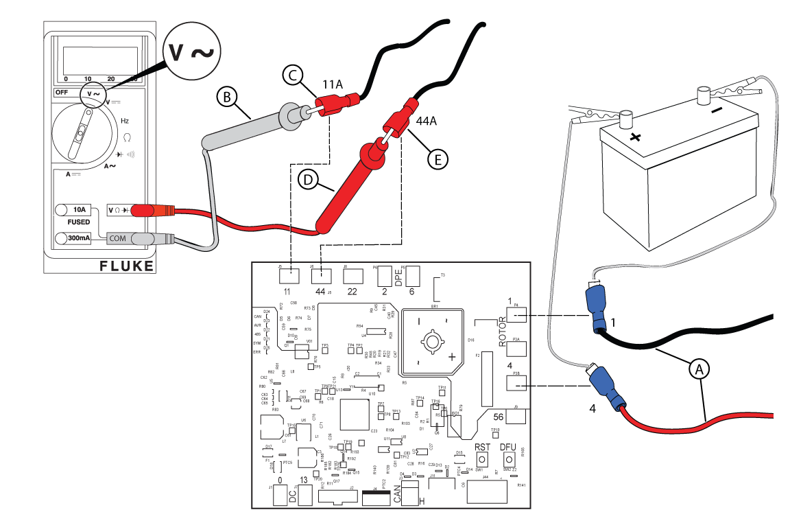
Figure 55 - Press STOP/CONFIG on the controller.
-
Check DC Amperage
NOTICE - The Check DC Amperage test should only be conducted if BOTH the power and excitation winding tests fail to meet specifications.
NOTICE - Normal readings are 1.0-1.5 amps (12-13 kW) or 0.6-0.75 amps (17-26 kW).
- What will be used for the DC amperage check?
- Digital Multimeter - Set to read DC amperage. Move the red test lead to the 10 amp post. Disconnect the jumper wire between the negative battery post and Wire 1. Connect one lead to the negative battery post and the other to Wire 1. Measure the static amp draw and write down the results. Go to step 4.
- DC Amp Clamp Meter (Recommended) - Set to read DC amperage. Capture Wire 1 in the jaw of the meter. Measure the static amp draw and write down the results.
- Press START/SELECT on the controller to start the engine.
- Measure the DC amperage and write down the value that best describes your results: Zero, Low, Normal (1.0-1.5 for 12-13kW | 0.6-0.75 for 17-26kW), or High.
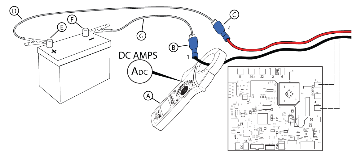
Figure 57 - Using the Smart AVR diagnostic table, find the column (A-G) that matches the values you wrote down for AC voltage tests and DC amperage. Replace the component indicated. Test again. NOTICE - Contact Briggs & Stratton Technical Support to receive prior authorization before installing a new rotor or stator.
- Press START on the controller. Does the engine have correct voltage?
- Yes - Go to Perform System Start-up and Final Controller Checks, found in the Installation & Start-up Support section.
- No - Return to the beginning of Generator Does Not Produce Voltage.
NOTICE - If you reach this point of the diagnostics twice, call Briggs & Stratton Technical Support for further instructions.
- What will be used for the DC amperage check?
Symptom: Improper Frequency, or Electronic Governor issues
Potential Cause: Generator Overspeed or Underspeed
ALARM(S): Fail to Start Alarm + Over Speed/Frequency, High Voltage Failure
-
Verify proper voltage LOAD-side
Action: (refer to applicable Service Bulletin and AVR Firmware sections below)
-
Check the Frequency
NOTICE - General images are shown and may not match your unit.
- Locate the generator circuit breaker and remove the breaker cover plate (if not already removed).
- Install a 15 amp fuse in the controller if removed.
- Set the generator circuit breaker to the OFF (Open) position.
- Push START/SELECT on the controller to start the engine.
- Set Digital Multimeter to read frequency. Connect the meter test leads to the breaker. Is 60 Hz present at the line side of the circuit breaker?
- Yes - Go to step 6.
- No - Go to Check the Electronic Governor. NOTICE - 180 Hz is not possible. Check the meter or use a tiny tachometer to check engine RPMs.
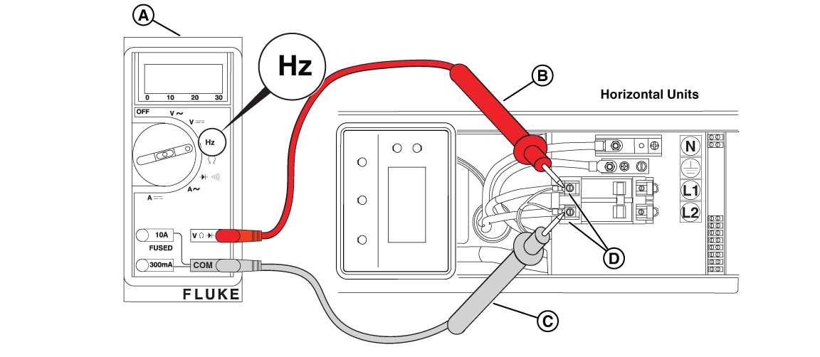
Figure 58 - Obtain a Digital Tachometer and Hour Meter. Install as follows: insert the solder lug of the white wire under the engine or frame bolt for suitable ground, and tightly coil the red wire over an insulated section of the spark plug cable three to four turns.
- Back probe Pin 29 (GENSET I/P Y, Wire 44C) and Pin 30 (GENSET I/P R, Wire 11C) at the back of the controller. Is 60 Hz present?
- Yes (and it is displayed on the controller LCD) - Go to Generator Runs Rough.
- Yes (but it is NOT displayed on the controller LCD) - Install a new controller. Test again.
- No - Repair or replace the wiring between the circuit breaker and the controller. Test again.
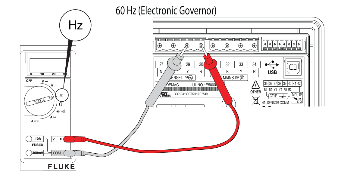
Figure 59
-
Check the Electronic Governor
- Press STOP/CONFIG on the controller and remove the 15 amp fuse.
- Perform a sweep test (see the controller Operation Manual for instructions). Does the stepper motor shaft move freely without sticking?
- Yes - Resistance testing of the stepper motor windings is required. Disconnect the electronic governor from the controller and go to step 3.
- No - Inspect the stepper motor and linkages for any binding or interference with bulkhead engine components. Repair or replace as necessary. Test again.
- Disconnect the connector from the controller and set Digital Multimeter to read ohms. Place one lead on Terminal 1 (Wire 8 - Yellow) and the other on Terminal 2 (Wire 9 - Black). Is resistance around 40 ohms?
- Yes - Go to step 4.
- No - Inspection of the wires between the stepper motor and controller is needed. Disconnect the electronic governor from the controller and go to step 4.
- Place one lead on Terminal 3 (Wire 10 - Blue) and the other on Terminal 4 (Wire 12 - White). Is resistance around 40 ohms?
- Yes - Install a new controller. Return to step 1 and test again. If you return to this point, go to step 5.
- No - Repair or replace Terminal 3 (Wire 10 - Blue) and/or Terminal 4 (Wire 12 - White). Test again.
- Can an engine idle speed of 3600 RPM be obtained?
- Yes - Go to Generator Runs Rough.
- No - See the appropriate Engine Service Manual.
NOTICE - If necessary, call Briggs & Stratton Technical Support for assistance.
Generator Starts and Runs For No Reason
NOTICE - Whenever "Test again" appears, install the 15 amp fuse (see your generator's installation and operator's manual for the fuse location), if removed.
If a test passes, review the full linear logic steps found in the Service Call & Maintenance Best Practices section.
Symptom: With Utility Power Present, Generator Starts/Runs Immediately
Potential Cause: Missing or faulty wires from fuse block in ATS, to Terminals 25 and 26 at the Generator; Utility Sense fuses have blown in ATS
ALARM(S): N/A
-
GC-1030 Series Controller: Confirm MAINS Status (Voltage on L1/L2)
Using the up/down arrows on the GC-1030 Series Controller, navigate to the MAINS screen and determine the MAINS status. Does the Controller display MAINS FAILED?
- Yes - Go to Check Utility Voltage Input (ATS Wiring & Fuses only).
- No - The generator may be in a Weekly Exercise or 45 Minute Burn Off.
-
Check Utility Voltage Input (ATS Wiring & Fuses only)
- Measure AC voltage on the bottom side of the two transfer switch fuses. Is approximately 240 VAC present?
- Yes - Repair or replace the wiring between the transfer switch and generator. Test again.
- No - Go to step 2.
Figure 15 - Measure AC voltage on the top side of the two transfer switch fuses. Is approximately 240 VAC present?
- Yes - Remove the fuses and test for continuity. Replace the open fuse(s). Test again. NOTICE - Before replacing the fuses, turn off utility power and verify no continuity to ground is present. If continuity to ground is present, check for wire shorts or a failed battery charger, warmer, or controller.
- No - Repair or replace transfer switch wiring. Test again.
Figure 16
- Measure AC voltage on the bottom side of the two transfer switch fuses. Is approximately 240 VAC present?
GC-1030 Series Controller Alarms & Event Log
Nearly 30 different Alarms are programmed on the Generator Controller. The standby generator includes sensors that automatically stop the generator in potentially damaging conditions.
GC-1030 Series Controller Alarms
-
Alternator Input Lost
Potential Root Cause(s): Loss of alternator output voltage is present or the controller is not recognizing the output voltage.
-
Amb Temp (Pin 24) Ckt Open
Potential Root Cause(s): Wire 57 (I/P: ANLG TEMP/DIG G) is not connected either on controller or relay board.
-
Auto Exercise Skipped
Potential Root Cause(s): Ambient temperature is below 40 degrees Fahrenheit.
-
AVR Fault
Potential Root Cause(s): Controller does not recognize the AVR (CANbus) or the AVR is failing.
-
Battery Over Voltage
Potential Root Cause(s): Voltage at controller Terminals 1 and 2 is greater than 15 VDC (shutdown alarm).
-
Battery Under Voltage
Potential Root Cause(s): Voltage at controller Terminals 1 and 2 is less than 10 VDC (warning alarm).
-
Emergency Stop
Potential Root Cause(s): Jumper is removed from generator Terminals 11 and 12, Wires 100A and/or 100B are removed from Terminals 11 and 12 and/or the relay board (E-Stop Terminals 1 and 2), Wire 100C is obstructed between relay board Terminal 3 (E-Stop) and controller Terminal 25 (Pin 9, I/P: ANLG FL/DIG H).
-
Extended Over Load Trip
Potential Root Cause(s): Too much load is being put on the generator.
-
Fail to Start
Potential Root Cause(s): The generator does not start after pressing the START/SELECT button on the controller a number of times.
-
Fail to Stop
Potential Root Cause(s): The generator does not stop after pressing STOP/CONFIG on the controller.
-
Gross Over Speed
Potential Root Cause(s): Engine speed significantly exceeds the normal operating RPM threshold.
-
High Engine Temperature Switch
Potential Root Cause(s): Engine block exceeds around 300 degrees Fahrenheit, engine seals (for air-flow) are eroded, air flow is blocked, continuity between terminals on the switch is failing (cold engine), or Wire 95 (Dig I/P E) is touching ground.
-
High Voltage Failure
Potential Root Cause(s): Voltage generated during the auto exercise is too high. Recreate the exercise and monitor the voltage at the generator circuit breaker.
-
Low Oil Pressure Switch
Potential Root Cause(s): Generator unit is low on oil, no oil pressure is present, the oil filter is clogged, a bad oil psi switch is present (continuity to ground with psi present), or Wire 85 (Dig I/P D) is touching ground.
-
Low Voltage Failure
Potential Root Cause(s): Voltage generated during the auto exercise is too low. Recreate the exercise and monitor the voltage at the generator circuit breaker.
-
Low Voltage Warning
Potential Root Cause(s): Voltage generated during the auto exercise is too low. Recreate the exercise and monitor the voltage at the generator circuit breaker.
-
Maintenance Due
Potential Root Cause(s): Exceeded the maintenance alarm setpoint (either hours of generator run time or the set due date). Enter configuration to reset the maintenance alarm.
-
Over Current
Potential Root Cause(s): Load on the generator has exceeded the current rating of the circuit breaker.
-
Over Frequency
Potential Root Cause(s): Frequency exceeds 60 Hz at the line side of the circuit breaker and/or the controller.
-
Over Load
Potential Root Cause(s): Too much load is present on the generator circuit breaker.
-
Over Speed
Potential Root Cause(s): Engine speed exceeds 4,200 RPM at the controller.
-
R/L1 Phase Over Voltage
Potential Root Cause(s): Voltage between Terminal 30 (R) and the L1 contact on the circuit breaker exceeds 240 VAC or the AVR firmware is incorrect.
-
R/L1 Phase Under Voltage
Potential Root Cause(s): Voltage between Terminal 30 (R) and the L1 contact on the circuit breaker is below 240 VAC.
-
Speed Sensor I/P Lost
Potential Root Cause(s): Firmware update is required (review service bulletins), speed sensor wiring is touching ground, or a loss of fuel supply is present.
-
Unbalanced Load
Potential Root Cause(s): Generator units are rated at 50% load imbalance between phases. Imbalances between phases can be measured with an ammeter. Correct or move the breaker load(s) as necessary.
-
Under Frequency
Potential Root Cause(s): Frequency is less than 60 Hz at the line side of the circuit breaker and/or the controller.
-
Under Speed
Potential Root Cause(s): Engine speed is less than 3,400 RPM at the controller.
-
Y/L2 Phase Over Voltage
Potential Root Cause(s): Voltage between Terminal 29 (Y) and the L2 contact on the circuit breaker exceeds 240 VAC or the AVR firmware is incorrect.
-
Y/L2 Phase Under Voltage
Potential Root Cause(s): Voltage between Terminal 29 (Y) and the L2 contact on the circuit breaker is below 240 VAC.
GC-1030 Series Controller "Event Log"
The GC-1030 Series Controller will store up to 100 events in an event log.
-
Access the Event Log
Follow these instructions to access the event log from the controller:
- Press Stop/Config to enter Manual Mode
- Press and hold Stop/Config to begin accessing the Configuration settings
- Press Stop/Config to access Configuration in Read Mode
- Press and hold the up and down arrows simultaneously
Additional Resources
Installation & Start-up Support
Confirm Basic System Set-up (Preliminary Checks)
Confirm Engine Oil
-
Check Engine Oil Level
- Check that the engine has been filled to the correct level with the recommended oil. Is the oil at the correct level?
- Yes - Go to Confirm Battery, Circuit Breaker, 15A Fuse, and Controller.
- No - Slowly add oil until the correct oil level is reached. DO NOT OVERFILL.
- Check that the engine has been filled to the correct level with the recommended oil. Is the oil at the correct level?
Confirm Battery, Circuit Breaker, 15A Fuse, and Controller
-
Check Battery Connection and Polarity
- The positive battery cable (red) must be connected to the positive battery (+) post and the negative battery cable (black) must be connected to the negative battery (-) post. Is the battery correctly connected?
- Yes - Go to Check Circuit Breaker.
- No - Correctly connect the battery.
- The positive battery cable (red) must be connected to the positive battery (+) post and the negative battery cable (black) must be connected to the negative battery (-) post. Is the battery correctly connected?
-
Check Circuit Breaker
- Is the generator circuit breaker set to the ON (Closed) position?
- Yes - Go to Check Fuse and GC-1030 Series Controller.
- No - Set the generator circuit breaker to the ON (Closed) position.
- Is the generator circuit breaker set to the ON (Closed) position?
-
Check Fuse and GC-1030 Series Controller
- Is the 15 amp ATO type fuse installed in the controller?
- Yes - Go to step 2.
- No - Install the 15 amp ATO type fuse in the controller.
- Is the generator controller set to AUTO?
- Yes - Go to Check Fuel Delivery.
- No - Press AUTO/MANUAL on the controller. An LED illuminates to indicate that the system is in AUTO mode. Is a fault present on the controller?
- No - Go to Confirm Fuel Delivery Settings (Type), and Supply Pressure.
- Yes - Go to Using Linear Diagnostics for the corresponding fault displayed on the controller.
- Is the 15 amp ATO type fuse installed in the controller?
Confirm Fuel Delivery, Settings (Type), and Supply Pressure
-
Check Fuel Delivery
- Is sufficient fuel available in the fuel supply tank? NOTICE - Fuel is only present on units with a liquid propane (LP) supply tank.
- Yes - Go to step 2.
- No - Replenish the fuel supply.
- Are the main fuel supply valve and any in-line fuel shutoff valves open?
- Yes - Go to Check Fuel Pressure.
- No - Open the main fuel supply valve and any in-line fuel shutoff valves.
- Is sufficient fuel available in the fuel supply tank? NOTICE - Fuel is only present on units with a liquid propane (LP) supply tank.
-
Check Fuel Type (12-13kW Vertical Units)
- Remove the roof and front panel.
- For 13 kW units only: press the fuel selector toggle switch (A, Figure 3) on top of the field connection box to the correct position - LP or NG (B).
Figure 3 - Locate the main jet and idle jet on the engine. Jet settings are as follows:
12-13kW NG and LP Configurations Model Engine Frequency Fuel Type Main Jet Turns Idle Jet Turns 12kW BSPP 38 v/s 60 Hz NG 1/2 2-1/2 LP 0 1/4 13kW BSPP 38 v/s 60 Hz NG 1-3/8 3/8 LP 1/8 3/4
Figure 4 - To convert to either fuel: navigate to the SELECT PROFILE page in the controller configuration menu (Dealer Password required to change from NG to LP - available on the Power Portal), press START/SELECT to set the correct profile (e.g. "13KW_LP"), and press and hold STOP/CONFIG to save. NOTICE - For 13 kW Units: DO NOT change the fuel regulator setting - leave at factory NG setting.
Figure 5
-
Check Fuel Type (17-26kW Horizontal Units)
- Open the roof and remove the air inlet side end cap.
- Locate the fuel selector valve on top of the fuel pressure regulator. To convert fuel types: set the fuel selector lever to LP or NG, select LP or NG on the fuel selector switch, then navigate to the controller configuration menu and set the correct generator profile (e.g. "20KW_LP"). Press and hold STOP/CONFIG to save. NOTICE - Dealer Password required to change from NG to LP. Selecting a profile not intended for the generator can cause erratic operation and damage.
Figure 7
Figure 8
Figure 9
-
Check Fuel Supply Pressure
NOTICE - The generator inlet fuel pressure should be 11-14 inches WC (LP) or 3.5-7 inches WC (NG).
- Close the main fuel supply valve to stop the flow of fuel to the generator.
- Locate the installer-supplied fuel pressure test port closest to the generator. NOTICE - If no test port exists, see the installation manual for instructions. To proceed without a test port, go to step 4 of Check Fuel Solenoid and Thermal Fuses.
- Obtain an analog manometer. Remove the test port plug and install the manometer.
- Open the main fuel supply valve to start the flow of fuel to the generator.
- Inspect the manometer gauge. Is the generator inlet fuel pressure 11-14 inches WC (LP) or 3.5-7 inches WC (NG)?
- Yes - Go to Check Fuel Solenoid and Thermal Fuses.
- No - Repair or replace fuel delivery system. Test again.
NOTICE - No more than 0.5 inches WC drop should be seen between static and dynamic fuel pressure and the fuel reading should be stable.
Figure 32
Service Call & Maintenance Best Practices
After Arriving On-Site
-
Check-in with Customer
Gather information and see it for yourself:
- Customer description may not match symptom
- Control Panel indication may not be exact - check controller history
- Multiple faults at once
Check System Operation
These are some of the most common reasons a generator may fail to crank, start, or run. Complete each of the following tests before you go to Using Linear Diagnostics.
Preliminary Checks
- Check interior and exterior of the generator
- Check engine oil level
- Check battery connection and polarity
- Check circuit breaker, fuse and GC-1030 Controller (correct mode, and if an alarm is present)
- Check fuel delivery, pressure, and type/profile settings
Steps for each of these checks can be found in the Confirm Basic System Set-up (Preliminary Checks) section.
Using Linear Diagnostics (to Identify the Problem)
After inspecting and clearing any faults on the GC-1030 Series Controller, the following linear diagnostics methodology can be used to help you determine where the specific problem lies.
NOTICE - Verify that the 15 amp fuse is installed in the controller. Press and hold START/SELECT on the controller to crank and start the engine.
Linear Diagnostics
After inspecting and clearing any controller faults, proceed as follows:
-
Check the Controller for Error Messages
NOTICE - Make sure the controller is powered on and the PMD is in the ON position.
- If an alarm is present on the controller (status LED light is flashing), access the controller and record the displayed error message.
- Make sure the controller firmware is updated to the most recent version. To access the product information display and view the existing firmware version, press the down arrow twice on the controller.
- Clear the alarm by pressing the up and down arrows simultaneously.
- Refer to the GC-1030 Series Controller Alarms & Event Log for more details on the error messages, sections for correcting the alarm, and steps for accessing/reviewing the Controller Event Log.
-
1. Does the engine crank?
Tests include load testing the battery and confirming battery connections, verifying utility voltage input to the battery charger, and sufficient trickle charge (confirming battery charger is operational). Additional tests include confirming the starter relay signal and starter solenoid connection, and proper output at the Generator Controller and Relay Board components. Review the "Generator Does Not Start" section for basic troubleshooting steps.
-
2. Does the engine start?
Tests include confirming fuel items, such as checking fuel supply pressure, fuel solenoid and thermal fuses, and fuel pressure regulator option. The engine may exhibit failure to turn over fast enough. Additional verification tests include engine items, such as checking spark, crankcase vacuum, and/or checking and adjusting valve clearance. Review the "Generator Does Not Start" section for basic troubleshooting steps.
-
3. Is proper voltage present?
Tests include measuring generator voltage at the LOAD side of the circuit breaker, the control panel, and LINE side of the circuit breaker. Instructions for checking the winding resistance (Rotor, Stator, and Power Windings) and additional alternator tests, as well as performing an AVR Bypass Test (checking AC voltage and DC amperage) are also included in this section. Review either the "Generator Starts and then Shuts Down" or "Generator Does Not Produce Voltage" sections for basic troubleshooting steps.
-
4. Is proper frequency present?
Tests include checking the frequency at the LINE side of the circuit breaker, and control panel, as well as checking the electronic governor. Review either the "Generator Starts and then Shuts Down" or "Generator Does Not Produce Voltage" sections for basic troubleshooting steps.
-
5. Is a Low Oil Pressure or High Engine Temperature condition present?
Tests include checking for low engine oil pressure, and/or high engine temperature. Review the "Generator Starts then Shuts Down" section for basic troubleshooting steps.
-
6. Is the engine running abnormal?
Run the engine and observe its performance. If the engine runs smoothly perform the check cylinder balance and crankcase vacuum tests. Additional troubleshooting instructions can be found in the appropriate Engine Service Manual for engines that perform poorly. Review the "Generator Runs Rough" section for basic troubleshooting steps.
-
7. It's Fixed! What are the Final Checks?
Technicians are provided with questions to check and confirm the state of the standby generator, organized by Battery, Fuel, Electrical Controls, Physical, Security, and Load Test. Additional general information that technicians should note include Equipment (Generator and Transfer Switch), Owner, and Service information.
Requesting Advanced Technical Support
The Briggs & Stratton Technical Support team is available by phone or email, Monday-Friday, from 7:30 AM - 4:30 PM Central (CST).
-
Prior to Calling for Technical Support
When diagnosing a standby generator issue, be sure to utilize all resources available to you, including the Troubleshooting Worksheet and/or Electrical Troubleshooting and Repair Manual. Once you have exhausted all options and resources internal to your company, Briggs & Stratton Technical Support is available to assist.
Technical Support Specialists will ask for the following unit information:
- Technician Name and DDM # (from your company)
- Standby Generator Model and Serial number
- Basic unit information such as 12V battery voltage, fuel type/pressure, and Controller firmware settings
- Symptoms and the troubleshooting steps you have done so far
-
Wait for Agent, or Utilize Call Back option
Throughout the year, especially during Hurricane/Storm Season, wait times may increase. Technical Support provides a call back option where your spot in line is reserved, and an agent will call you back when they are available.
As of February 2025, new hold messages have been introduced assisting you with basic troubleshooting steps and product reminders. Please let us know if they are helpful.
-
Major Repairs (Requesting a Control Authorization Number)
For standby generators within their standard warranty period requiring major repair (e.g. engine, alternator, or controller replacement), a control authorization number may be required. Additional items requiring authorization may include, but are not limited to additional repair time, mileage, and/or site trip charge(s).
Before Leaving the Site
-
Check-in with Customer
Gather information and see it for yourself:
- Customer description may not match symptom
- Control Panel indication may not be exact - check controller history
- Multiple faults at once
-
Simulate an Outage
- Confirm the generator Controller is in AUTO mode, no fault codes are present, AND the generator circuit breaker is in the ON/CLOSED state.
- Close the lid of the generator.
- Request approval from the customer, after discussing the "simulated outage event" details.
- Remove the ATS outer panel to gain access to the Utility circuit breaker.
- Open, or turn OFF the Utility circuit breaker in the ATS. Power to the site/home will be removed!
- Confirm the engine start (ES) time delay: after 6 seconds, the generator should start.
- Confirm normal-to-emergency (N-to-E) transfer time delay: after 20-50 seconds the ATS contactor will transfer from the Utility position, to the Generator position.
- Verify generator power is being supplied to the site/home.
- Perform basic system checks at the Generator and ATS to verify system operation. Allow the generator to operate for a minimum of 5 minutes.
- Return to ATS and close, or turn ON the Utility circuit breaker.
- Confirm the emergency-to-normal (E-to-N) transfer time delay: after 10 seconds the system senses the utility power has returned, and the ATS contactor will transfer back to the Utility position (system must operate for a minimum 5 minutes before re-transferring).
- Confirm the engine cool-down time delay: the engine enters a five minute cool-down period after re-transfer, and the generator returns to a standby state.
- Confirm the generator Controller is in AUTO mode, no fault codes are present, AND the generator circuit breaker is in the ON/CLOSED state.
-
Record Service Call Information for Warranty Purposes
Record all service call information for warranty purposes, including equipment details (Generator and Transfer Switch), Owner information, and Service information prior to leaving the site.
-
Clean-up Areas In and Around the Generator
Items to clean up: ensure all tools and test equipment are removed from the generator enclosure, clean up any oil or fluids spilled during service, reinstall all panels and covers removed during troubleshooting, and confirm the generator enclosure is properly closed and secured.
Technical Support Resources
Critical Service Documents
Troubleshooting
Technical support documents are available to assist you when troubleshooting an air-cooled standby generator.
-
Troubleshooting Worksheet
Troubleshooting aid covering information utilized prior to and during conversations with Technical Support.
-
Electrical Troubleshooting & Repair Manual
This manual provides a comprehensive linear path to correctly diagnose most generator problems, including those units with a GC-1030 Series Controller.
Linear Logic Methodology
Before you start the diagnosis, answer the questions listed in the Introduction and Preliminary Checks sections before proceeding to the Using Linear Diagnostics section. This will determine the actual point at which to begin the diagnosis.Parts Removal and Installation instructions
Illustrations and detailed instructions for removing and installing various standby generator components are included, organized in sections for the 12-13kW vertical and 17-26kW horizontal units.
Parts Manual
Service Bulletins
Specific technical documentation may be available, in the form of a Service Bulletin. These items detail a condition on the standby generator and/or engine, as well as corrective action steps.
NOTE: A PowerPortal login is required to view Briggs & Stratton Service Bulletin documentation.
PowerProtect 13kW (040740 and 040746; Vertical Unit)
PowerProtect 18kW (040756; Horizontal Unit)
-
GC-1032R Controller (Service Part) Will No Longer Have Firmware Loaded
DSB1153
Any GC-1032 Controller service part manufactured AFTER January 01, 2024 will no longer have the firmware loaded. The data label on the back of the GC-1032R controller will display the manufacturing date. Consult the documentation to upload the appropriate firmware version to the GC-1032 Controller, using the SmartFlash tool.
View Document -
PowerProtect Air Cooled Generator Firmware Versions R4.00, R4.01, And R4.02
DSB1163
Air-cooled standby generators having R4.00, R4.01, or R4.02 firmware versions installed on the GC-1032 Controller may exhibit performance issues (e.g. exercise cycle does not execute properly). Consult the documentation to upload the appropriate firmware version to the GC-1032 Controller, using the SmartFlash tool.
View Document
PowerProtect 22 & 26kW (040780, 040786, 040800, 040806; Horizontal Units)
-
GC-1032R Controller (Service Part) Will No Longer Have Firmware Loaded
Review the information listed for DSB1153 above.
-
PowerProtect Air Cooled Generator Firmware Versions R4.00, R4.01, And R4.02
Review the information listed for DSB1163 above.
-
AVR Assemblies (Service Part) 772378 and 84010843 Compatibility
DSB1160
Multiple firmware versions are available for the Smart AVR, resulting in specific compatibility conditions. Consult the documentation to verify that the correct AVR firmware version is installed after servicing/replacing the generator's Smart AVR.
View Document
Software & Firmware Support
This section includes instructions on how to install and use the software and firmware for use on Briggs & Stratton PowerProtect standby generators.
-
AVR Firmware
Qualified service technicians must use the Firmware Programmer software to program the Smart AVR.
Firmware Programmer - Hardware/Software Requirements
- Smart AVR Assembly
- USB 2.0 standard B-type cable, also known as a USB Printer Cable
- Windows based PC or Laptop (NO tablets, smartphones, or Apple OS)
- Download the latest A1.3 or A1.4 Firmware to your computer PRIOR to traveling onsite
NOTE: The same Firmware Programmer v1.1 software used for programming the Briggs & Stratton Standard Controller may also be used to program and verify programming on the Smart AVR.
-
GC-1030 Series Controller Firmware
Qualified service technicians must use the Smart Flash software to program the GC-1030 Series GENSET Controller.
Smart Flash - Hardware/Software Requirements
- GC1030 Series Controller (GC1032R running 3.18 or higher, GC1032 running 2.10 or higher, GC1031 running 8.00 or higher)
- USB 2.0 standard B-type cable, also known as a USB Printer Cable
- Windows based PC or Laptop (NO tablets, smartphones, or Apple OS)
- Stable internet connection, or download the latest firmware using the "Download from Server" button PRIOR to traveling onsite
SmartFlash Software Security Code: To use the SmartFlash software, users will be prompted to enter a Security Code (1031). This will only be requested once, after installing/re-installing the software application.
Tools & Parts: Recommended and Specialty Items
The following recommended and specialty tools may be necessary for servicing this standby generator.
-
Common Tools
- Digital Multimeter
- Analog Manometer
- Basic Hand Tools
-
Specialty Tools
- Briggs & Stratton Digital Tachometer and Hour Meter (Part No. 19598)
- Briggs & Stratton Ignition Tester (Part No. 19368)
- Briggs & Stratton Valve Adjustment Set (Part No. 19465) or equivalent set of 13mm offset box end wrench, T40 T-handle Torx wrench, and 5mm T-handle Allen wrench
- Briggs & Stratton Tang Adjusting Tool (Part No. 19480)
- Briggs & Stratton Jet Screwdriver Set (Part No. 19570)
- Briggs & Stratton Digital Volt/Ohm Meter with Amp Clamp (Part No. 19602)
- Feeler Gauge set (4-Blade Feeler Gauge Tool) or equivalent basic feeler gauge set (Part No. 19638)
"Fast Moving" Spare Parts
-
PowerProtect 13kW
Engine Parts
- 841359 - Air Cleaner
- 737434 - Spark Plug (2)
- 842921 - Oil Filter
- 806039S - Valve Cover Gasket (2)
- 807085 - Valve Cover Sealing Washer (4)
- 842622 - Cyl Head Gasket (2)
- 691613 - Exhaust Gasket (2)
- 844717 - Starter Motor
- 841281 - Oil Pressure Switch
Cold Weather Kit
- 6921 - Battery Warmer
- 6922 - Oil Warmer
Generator Parts
- 311316GS - Circuit Breaker
- 84007051 - Control Panel (GC-1030 Series Controller)
- 1985736GS - Control Panel Fuse
- 84010843 - Voltage Regulator (AVR)
- 772376 - Battery Charger
- 772336 - Relay Board
- 195130GS - Engine Temperature Switch
- 691656 - Starter Solenoid Relay
- 84006385 - Fuel Regulator
- 84011112 - Fuel Flex Hose
- 314290GS - Key Set
-
PowerProtect 18-26kW
Engine Parts
- 841856 - Air Cleaner
- 792015 - Spark Plug (2)
- 842921 - Oil Filter
- 809732 - Valve Cover Gasket (2)
- 809730 - Cyl Head Gasket (2)
- 809872 - Exhaust Gasket (2)
- 84008634 - Starter Motor
- 84008635 - Starter Solenoid
- 841281 - Oil Pressure Switch
Cold Weather Kit
- 6840 - Oil Sump Warmer
- 6845 - Fuel Regulator Heater
- 6869 - Battery Warmer
Generator Parts
- 316187GS - Circuit Breaker (18kW)
- 311318GS - Circuit Breaker (22kW)
- 84007090 - Circuit Breaker (26kW)
- 84007051 - Control Panel (GC-1030 Series Controller)
- 1985736GS - Control Panel Fuse
- 84010843 - Voltage Regulator (AVR) for 18kW, 22kW (040780, 040781, 040786) and 26kW (040800, 040801, 040806)
- 772378 - Smart AVR for 26kW (040658, 040664, 040665, 040694)
- 772376 - Battery Charger
- 772336 - Relay Board
- 204426GS - Engine Temperature Switch
- 772333 - Starter Solenoid Relay
- 84006385 - Fuel Regulator
- 84011112 - Fuel Flex Hose
- 314290GS - Key Set
-
100-200A Transfer Switches
Boards
- 771701 - ACCM Board
- 770434 - Circuit Board (TRCM)
Transfer Switch Contacts
- 314867GS - 100 Amp Contactor
- 315050GS - 150/200 Amp Contactor
Miscellaneous
- 192151GS - Fuse Holder
- 205110GS - Fuse
- 208106GS - Current Transformers
Power Academy
The Briggs & Stratton Power Academy is a virtual learning hub offering various types of training options for selling, installing and servicing energy solutions products. Self-paced eLearning, live virtual and in-person courses are offered to fit your schedule and learning style.
The Briggs & Stratton Power Portal
ThePowerPortal.com is a secure, password protected website created in partnerships with our dealers, distributors, suppliers and customers. Access to brand information is available for many of the Briggs & Stratton family product lines, including standby generators.
-
Model Search
Using the Model Search feature on the PowerPortal, technicians can review product information, model specifications as well as access specific documentation including illustrated parts lists, operators & installation manuals, and warranty & repair manuals.
-
eParts - Interactive Parts Lookup tool
eParts is a web based system for retrieving information about parts from Briggs & Stratton Energy Solutions. eParts lets you look up a standby generator and an engine model and display an Illustrated Parts List (IPL) of its assemblies.
You can: view the document attachments for the model, view the IPL for each assembly, enter a part number to view which standby generator model it is associated with, and access additional purchasing benefits from the main account login (DDM #).
-
Power Channel
Created for all Briggs & Stratton model engines and various product applications, The Power Channel provides technical video content and access to certifications, such as the VANGUARD Service Technician (VST) and Master Service Technician (MST) certifications.
Account Types
Two (2) different types of user accounts are available on the PowerPortal. The Primary Account Holder (DDM #) account is created when an agreement with Briggs & Stratton is completed, from a Dealer, Distributor or Authorized Installer business. Users with this login can create Technician Accounts that are managed under the primary account.
-
Primary Account Holder (DDM #)
A primary account for the PowerPortal was created when you agreed to become an authorized partner with Briggs & Stratton. This is commonly referred to as a DDM account.
- Account information including open/closed invoices for your company, available from the Dealer Dashboard
- Product registration submissions and product service history
- Warranty claim submission & claim status check
- Sales & Marketing portal for ordering product brochures, specification sheets, and other literature and advertisement assets
- Create "technician accounts" for all staff members at your company
-
Technician Accounts
Something just as powerful on the PowerPortal is a Technician Account, which is created and managed under the primary account. These accounts are well suited for technicians or salespersons working at your company, needing access to the following items:
- Interactive web based parts look-up for all brands (illustrated parts lists)
- Robust technical support documentation including operators & installation manuals, service bulletins, and repair manuals
- Annual maintenance checklists for air-cooled and liquid-cooled standby generators
NOTE: Technician accounts are NOT able to place orders or file warranties, and ARE empowered to access the tools necessary to support your customers!
If you need assistance logging into the PowerPortal, or creating a technician account, click the button below. You will be asked to supply the primary PowerPortal login ID (DDM #) and phone number contact information, as well as the technician's first and last name and their email address (cannot be the company's main email address).
Still need help?
Contact our standby generator Technical Support team at techsupport@basco.com, or 800-759-2744.
You will be asked to provide the standby generator’s Model and Serial Numbers, and must have a Dealer ID number when calling.